正在加载图片...
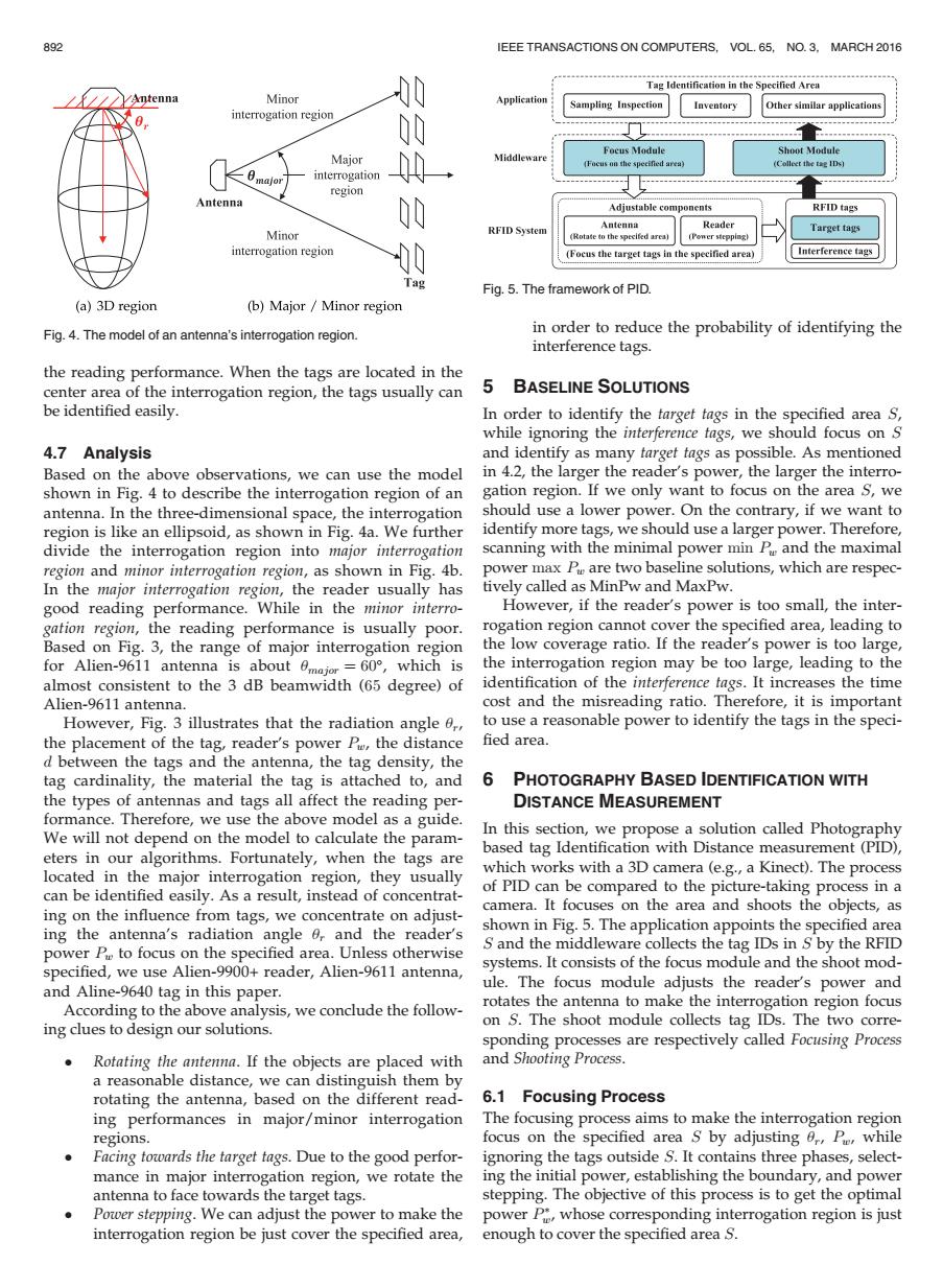
892 IEEE TRANSACTIONS ON COMPUTERS,VOL.65,NO.3,MARCH 2016 Tag Identification in the Specified Aren /知tenna Minor 00 Application Sampling Inspection Inventory Other similar applications interrogation region 00 下oc8I0dule Shoot Module Major Focus on the specified area) interrogation region Antenna 00 Adjustable components RFID tags Minor RFID System A口teia Reader Target tags (Rotate to the xpecifed area) (Power stepping) interrogation region 0 (Focus the target tags in the specified area) Interference tags ag Fig.5.The framework of PID. (a)3D region (b)Major Minor region Fig.4.The model of an antenna's interrogation region. in order to reduce the probability of identifying the interference tags. the reading performance.When the tags are located in the center area of the interrogation region,the tags usually can 5 BASELINE SOLUTIONS be identified easily. In order to identify the target tags in the specified area S, while ignoring the interference tags,we should focus on S 4.7 Analysis and identify as many target tags as possible.As mentioned Based on the above observations,we can use the model in 4.2,the larger the reader's power,the larger the interro- shown in Fig.4 to describe the interrogation region of an gation region.If we only want to focus on the area s,we antenna.In the three-dimensional space,the interrogation should use a lower power.On the contrary,if we want to region is like an ellipsoid,as shown in Fig.4a.We further identify more tags,we should use a larger power.Therefore, divide the interrogation region into major interrogation scanning with the minimal power min P and the maximal region and minor interrogation region,as shown in Fig.4b. power max P are two baseline solutions,which are respec- In the major interrogation region,the reader usually has tively called as MinPw and MaxPw. good reading performance.While in the minor interro- However,if the reader's power is too small,the inter- gation region,the reading performance is usually poor. rogation region cannot cover the specified area,leading to Based on Fig.3,the range of major interrogation region the low coverage ratio.If the reader's power is too large, for Alien-9611 antenna is about 0major=60,which is the interrogation region may be too large,leading to the almost consistent to the 3 dB beamwidth (65 degree)of identification of the interference tags.It increases the time Alien-9611 antenna. cost and the misreading ratio.Therefore,it is important However,Fig.3 illustrates that the radiation angle 0, to use a reasonable power to identify the tags in the speci- the placement of the tag,reader's power Pe,the distance fied area. d between the tags and the antenna,the tag density,the tag cardinality,the material the tag is attached to,and 6 PHOTOGRAPHY BASED IDENTIFICATION WITH the types of antennas and tags all affect the reading per- DISTANCE MEASUREMENT formance.Therefore,we use the above model as a guide. We will not depend on the model to calculate the param- In this section,we propose a solution called Photography based tag Identification with Distance measurement(PID), eters in our algorithms.Fortunately,when the tags are located in the major interrogation region,they usually which works with a 3D camera (e.g.,a Kinect).The process can be identified easily.As a result,instead of concentrat- of PID can be compared to the picture-taking process in a camera.It focuses on the area and shoots the objects,as ing on the influence from tags,we concentrate on adjust- ing the antenna's radiation angle 0,and the reader's shown in Fig.5.The application appoints the specified area power P to focus on the specified area.Unless otherwise S and the middleware collects the tag IDs in S by the RFID specified,we use Alien-9900+reader,Alien-9611 antenna, systems.It consists of the focus module and the shoot mod- ule.The focus module adjusts the reader's power and and Aline-9640 tag in this paper. According to the above analysis,we conclude the follow- rotates the antenna to make the interrogation region focus ing clues to design our solutions. on S.The shoot module collects tag IDs.The two corre- sponding processes are respectively called Focusing Process Rotating the antenna.If the objects are placed with and Shooting Process. a reasonable distance,we can distinguish them by rotating the antenna,based on the different read- 6.1 Focusing Process ing performances in major/minor interrogation The focusing process aims to make the interrogation region regions. focus on the specified area s by adjusting 0,Pe,while Facing towards the target tags.Due to the good perfor- ignoring the tags outside S.It contains three phases,select- mance in major interrogation region,we rotate the ing the initial power,establishing the boundary,and power antenna to face towards the target tags. stepping.The objective of this process is to get the optimal Power stepping.We can adjust the power to make the power P,whose corresponding interrogation region is just interrogation region be just cover the specified area,enough to cover the specified area s.the reading performance. When the tags are located in the center area of the interrogation region, the tags usually can be identified easily. 4.7 Analysis Based on the above observations, we can use the model shown in Fig. 4 to describe the interrogation region of an antenna. In the three-dimensional space, the interrogation region is like an ellipsoid, as shown in Fig. 4a. We further divide the interrogation region into major interrogation region and minor interrogation region, as shown in Fig. 4b. In the major interrogation region, the reader usually has good reading performance. While in the minor interrogation region, the reading performance is usually poor. Based on Fig. 3, the range of major interrogation region for Alien-9611 antenna is about umajor ¼ 60, which is almost consistent to the 3 dB beamwidth (65 degree) of Alien-9611 antenna. However, Fig. 3 illustrates that the radiation angle ur, the placement of the tag, reader’s power Pw, the distance d between the tags and the antenna, the tag density, the tag cardinality, the material the tag is attached to, and the types of antennas and tags all affect the reading performance. Therefore, we use the above model as a guide. We will not depend on the model to calculate the parameters in our algorithms. Fortunately, when the tags are located in the major interrogation region, they usually can be identified easily. As a result, instead of concentrating on the influence from tags, we concentrate on adjusting the antenna’s radiation angle ur and the reader’s power Pw to focus on the specified area. Unless otherwise specified, we use Alien-9900+ reader, Alien-9611 antenna, and Aline-9640 tag in this paper. According to the above analysis, we conclude the following clues to design our solutions. Rotating the antenna. If the objects are placed with a reasonable distance, we can distinguish them by rotating the antenna, based on the different reading performances in major/minor interrogation regions. Facing towards the target tags. Due to the good performance in major interrogation region, we rotate the antenna to face towards the target tags. Power stepping. We can adjust the power to make the interrogation region be just cover the specified area, in order to reduce the probability of identifying the interference tags. 5 BASELINE SOLUTIONS In order to identify the target tags in the specified area S, while ignoring the interference tags, we should focus on S and identify as many target tags as possible. As mentioned in 4.2, the larger the reader’s power, the larger the interrogation region. If we only want to focus on the area S, we should use a lower power. On the contrary, if we want to identify more tags, we should use a larger power. Therefore, scanning with the minimal power min Pw and the maximal power max Pw are two baseline solutions, which are respectively called as MinPw and MaxPw. However, if the reader’s power is too small, the interrogation region cannot cover the specified area, leading to the low coverage ratio. If the reader’s power is too large, the interrogation region may be too large, leading to the identification of the interference tags. It increases the time cost and the misreading ratio. Therefore, it is important to use a reasonable power to identify the tags in the speci- fied area. 6 PHOTOGRAPHY BASED IDENTIFICATION WITH DISTANCE MEASUREMENT In this section, we propose a solution called Photography based tag Identification with Distance measurement (PID), which works with a 3D camera (e.g., a Kinect). The process of PID can be compared to the picture-taking process in a camera. It focuses on the area and shoots the objects, as shown in Fig. 5. The application appoints the specified area S and the middleware collects the tag IDs in S by the RFID systems. It consists of the focus module and the shoot module. The focus module adjusts the reader’s power and rotates the antenna to make the interrogation region focus on S. The shoot module collects tag IDs. The two corresponding processes are respectively called Focusing Process and Shooting Process. 6.1 Focusing Process The focusing process aims to make the interrogation region focus on the specified area S by adjusting ur, Pw, while ignoring the tags outside S. It contains three phases, selecting the initial power, establishing the boundary, and power stepping. The objective of this process is to get the optimal power P w, whose corresponding interrogation region is just enough to cover the specified area S. Fig. 4. The model of an antenna’s interrogation region. Fig. 5. The framework of PID. 892 IEEE TRANSACTIONS ON COMPUTERS, VOL. 65, NO. 3, MARCH 2016