正在加载图片...
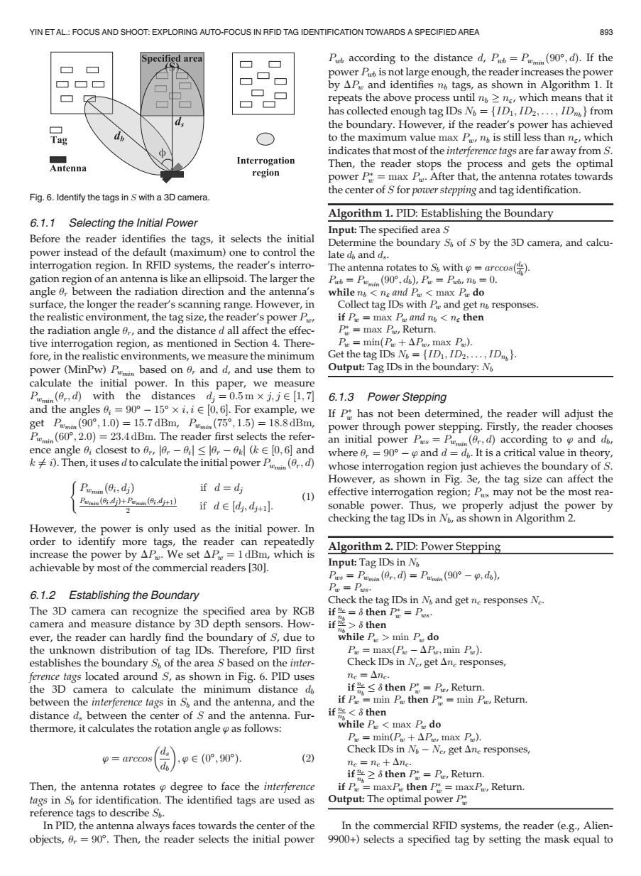
YIN ETAL:FOCUS AND SHOOT:EXPLORING AUTO-FOCUS IN RFID TAG IDENTIFICATION TOWARDS A SPECIFIED AREA 893 Specified area Paccording to the distance d,P=P(,d).If the power P is not large enough,the reader increases the power by APe and identifies no tags,as shown in Algorithm 1.It repeats the above process until n>ne,which means that it has collected enough tag IDs N =[ID1,ID2,...,ID from the boundary.However,if the reader's power has achieved Tag to the maximum value max Pn is still less than n,which indicates that most of the interference tags are far away from S. Interrogation Antenna Then,the reader stops the process and gets the optimal region power P=max P.After that,the antenna rotates towards the center of S for power stepping and tag identification. Fig.6.Identify the tags in S with a 3D camera Algorithm 1.PID:Establishing the Boundary 6.1.1 Selecting the Initial Power Input:The specified area S Before the reader identifies the tags,it selects the initial Determine the boundary S of S by the 3D camera,and calcu- power instead of the default(maximum)one to control the late d,and d.. interrogation region.In RFID systems,the reader's interro- The antenna rotates to So with=arccos() gation region of an antenna is like an ellipsoid.The larger the Pw=Penn(90°,do,Pe=Pa,n6,=0. angle 6,between the radiation direction and the antenna's while n ne and Pe max Pu do surface,the longer the reader's scanning range.However,in Collect tag IDs with Pe and get n responses. the realistic environment,the tag size,the reader's power Pr if Pe=max P and n<ne then the radiation angle r,and the distance d all affect the effec- P max P,Return. tive interrogation region,as mentioned in Section 4.There- Pu min(P +AP,max Pu). fore,in the realistic environments,we measure the minimum Get the tag IDs N =[ID1,ID2,...,ID). power (MinPw)Pin based on 0,and d,and use them to Output:Tag IDs in the boundary:N calculate the initial power.In this paper,we measure Pummin (0,d)with the distances dj=0.5m x j,je [1,7] 6.1.3 Power Stepping and the angles0=90°-l5°×i,i∈[0,G.For example,,we If p*has not been determined,the reader will adjust the get Pumin(90°,1.0)=15.7dBm,Pmm(75°,1.5)=18.8dBm, power through power stepping.Firstly,the reader chooses Pmin(60,2.0)=23.4dBm.The reader first selects the refer- an initial power Ps=Pin(0,,d)according to and do, ence angle 0;closest to r,0-<0r-0 E[0,6]and where 0,=90-and d=do.It is a critical value in theory, )Then,it uses dto calculate the initial power P d) whose interrogation region just achieves the boundary of S. However,as shown in Fig.3e,the tag size can affect the Pmindj) if d=dj effective interrogation region;Ps may not be the most rea- Pmn(,d+Pmn(,di+1】 (1) if deldj,dti]. sonable power.Thus,we properly adjust the power by checking the tag IDs in No,as shown in Algorithm 2. However,the power is only used as the initial power.In order to identify more tags,the reader can repeatedly increase the power by AP.We set AP=1dBm,which is Algorithm 2.PID:Power Stepping achievable by most of the commercial readers [301. Input:Tag IDs in N Ps=Pmin(日r,d=Pumin(90°-p,d6) 6.1.2 Establishing the Boundary Pu Pus. Check the tag IDs in N and get ne responses Ne. The 3D camera can recognize the specified area by RGB if=8 then P=P. camera and measure distance by 3D depth sensors.How- if些>$then ever,the reader can hardly find the boundary of S,due to while Pe>min P do the unknown distribution of tag IDs.Therefore,PID first Pu max(Pu -APu;min P). establishes the boundary S of the area S based on the inter- Check IDs in Ne,get Ane responses, ference tags located around S,as shown in Fig.6.PID uses ne=△nc. the 3D camera to calculate the minimum distance d if <8 then P Pu,Return. between the interference tags in S and the antenna,and the if Pie min P then P=min Pe,Return. distance d,between the center of S and the antenna.Fur- if "<8 then thermore,it calculates the rotation angle as follows: while P<max P do Pue min(Pu +AP,max P). Check IDs in N-Ne,get Ane responses, o=arccos ,p∈(0°,90) (2) ne=nc+△nc. if >8 then P Pu,Return. Then,the antenna rotates degree to face the interference if Pi=maxP then P=max Pe,Return. tags in S for identification.The identified tags are used as Output:The optimal power P reference tags to describe S. In PID,the antenna always faces towards the center of the In the commercial RFID systems,the reader (e.g.,Alien- objects,0,=90.Then,the reader selects the initial power 9900+)selects a specified tag by setting the mask equal to6.1.1 Selecting the Initial Power Before the reader identifies the tags, it selects the initial power instead of the default (maximum) one to control the interrogation region. In RFID systems, the reader’s interrogation region of an antenna is like an ellipsoid. The larger the angle ur between the radiation direction and the antenna’s surface, the longer the reader’s scanning range. However, in the realistic environment, the tag size, the reader’s power Pw, the radiation angle ur, and the distance d all affect the effective interrogation region, as mentioned in Section 4. Therefore, in the realistic environments, we measure the minimum power (MinPw) Pwmin based on ur and d, and use them to calculate the initial power. In this paper, we measure Pwmin ður; dÞ with the distances dj ¼ 0:5 m j; j 2 ½1; 7 and the angles ui ¼ 90 15 i; i 2 ½0; 6. For example, we get Pwmin ð90; 1:0Þ ¼ 15:7 dBm, Pwmin ð75; 1:5Þ ¼ 18:8 dBm, Pwmin ð60; 2:0Þ ¼ 23:4 dBm. The reader first selects the reference angle ui closest to ur, jur uijjur ukj (k 2 ½0; 6 and k 6¼ i). Then, it uses d to calculate the initial power Pwmin ður; dÞ Pwmin ðui; djÞ if d ¼ dj Pwmin ðui;djÞþPwmin ðui;djþ1Þ 2 if d 2 ½dj; djþ1: ( (1) However, the power is only used as the initial power. In order to identify more tags, the reader can repeatedly increase the power by DPw. We set DPw ¼ 1 dBm, which is achievable by most of the commercial readers [30]. 6.1.2 Establishing the Boundary The 3D camera can recognize the specified area by RGB camera and measure distance by 3D depth sensors. However, the reader can hardly find the boundary of S, due to the unknown distribution of tag IDs. Therefore, PID first establishes the boundary Sb of the area S based on the interference tags located around S, as shown in Fig. 6. PID uses the 3D camera to calculate the minimum distance db between the interference tags in Sb and the antenna, and the distance ds between the center of S and the antenna. Furthermore, it calculates the rotation angle ’ as follows: ’ ¼ arccos ds db ; ’ 2 ð0 ; 90 Þ: (2) Then, the antenna rotates ’ degree to face the interference tags in Sb for identification. The identified tags are used as reference tags to describe Sb. In PID, the antenna always faces towards the center of the objects, ur ¼ 90. Then, the reader selects the initial power Pwb according to the distance d, Pwb ¼ Pwmin ð90; dÞ. If the power Pwb is not large enough, the reader increases the power by DPw and identifies nb tags, as shown in Algorithm 1. It repeats the above process until nb n", which means that it has collected enough tag IDs Nb ¼ fID1; ID2; ... ; IDnbg from the boundary. However, if the reader’s power has achieved to the maximum value max Pw, nb is still less than n", which indicates that most of the interference tags are far away from S. Then, the reader stops the process and gets the optimal power P w ¼ max Pw. After that, the antenna rotates towards the center of S for power stepping and tag identification. Algorithm 1. PID: Establishing the Boundary Input: The specified area S Determine the boundary Sb of S by the 3D camera, and calculate db and ds. The antenna rotates to Sb with ’ ¼ arccosð ds db Þ. Pwb ¼ Pwmin ð90; dbÞ, Pw ¼ Pwb, nb ¼ 0. while nb < n" and Pw < max Pw do Collect tag IDs with Pw and get nb responses. if Pw ¼ max Pw and nb < n" then P w ¼ max Pw, Return. Pw ¼ minðPw þ DPw, max Pw). Get the tag IDs Nb ¼ fID1; ID2; ... ; IDnbg. Output: Tag IDs in the boundary: Nb 6.1.3 Power Stepping If P w has not been determined, the reader will adjust the power through power stepping. Firstly, the reader chooses an initial power Pws ¼ Pwmin ður; dÞ according to ’ and db, where ur ¼ 90 ’ and d ¼ db. It is a critical value in theory, whose interrogation region just achieves the boundary of S. However, as shown in Fig. 3e, the tag size can affect the effective interrogation region; Pws may not be the most reasonable power. Thus, we properly adjust the power by checking the tag IDs in Nb, as shown in Algorithm 2. Algorithm 2. PID: Power Stepping Input: Tag IDs in Nb Pws ¼ Pwmin ður; dÞ ¼ Pwmin ð90 ’; dbÞ, Pw ¼ Pws. Check the tag IDs in Nb and get nc responses Nc. if nc nb ¼ d then P w ¼ Pws. if nc nb > d then while Pw > min Pw do Pw ¼ maxðPw DPw; min PwÞ. Check IDs in Nc, get Dnc responses, nc ¼ Dnc. if nc nb d then P w ¼ Pw, Return. if Pw ¼ min Pw then P w ¼ min Pw, Return. if nc nb < d then while Pw < max Pw do Pw ¼ min(Pw þ DPw, max Pw). Check IDs in Nb Nc, get Dnc responses, nc ¼ nc þ Dnc. if nc nb d then P w ¼ Pw, Return. if Pw ¼ maxPw then P w ¼ maxPw, Return. Output: The optimal power P w In the commercial RFID systems, the reader (e.g., Alien- 9900+) selects a specified tag by setting the mask equal to Fig. 6. Identify the tags in S with a 3D camera. YIN ET AL.: FOCUS AND SHOOT: EXPLORING AUTO-FOCUS IN RFID TAG IDENTIFICATION TOWARDS A SPECIFIED AREA 893��