正在加载图片...
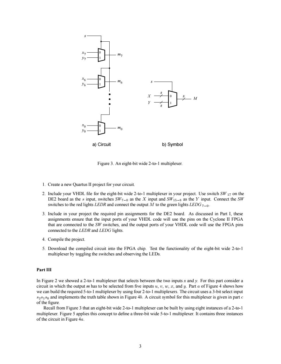
a)Circuit b)Symbol Figure 3.An eight-bit wide 2-to-1 multiplexer. 1.Create a new Quartus l project for your circuit swithes to the red lightsRand conect the outputMto the green lightsG 3.Include in your project the required pin assignments for the DE2 board.As discussed in Part I,these 4.Compile the project 5.Download the compiled circuit into the FPGA chip.Test the functionality of the eight-bit wide 2-to-1 multiplexer by togging the switches and observing the LEDs. PartII 盛omp eight-bit vide 2-to-1 insta oteecmng5ees multiplexe ia 0 1 s a) Circuit b) Symbol 0 1 0 1 m0 m6 m7 x6 x0 y6 y0 y7 x7 0 1 s M Y X 8 8 8 Figure 3. An eight-bit wide 2-to-1 multiplexer. 1. Create a new Quartus II project for your circuit. 2. Include your VHDL file for the eight-bit wide 2-to-1 multiplexer in your project. Use switch SW 17 on the DE2 board as the s input, switches SW7−0 as the X input and SW15−8 as the Y input. Connect the SW switches to the red lights LEDR and connect the output M to the green lights LEDG7−0. 3. Include in your project the required pin assignments for the DE2 board. As discussed in Part I, these assignments ensure that the input ports of your VHDL code will use the pins on the Cyclone II FPGA that are connected to the SW switches, and the output ports of your VHDL code will use the FPGA pins connected to the LEDR and LEDG lights. 4. Compile the project. 5. Download the compiled circuit into the FPGA chip. Test the functionality of the eight-bit wide 2-to-1 multiplexer by toggling the switches and observing the LEDs. Part III In Figure 2 we showed a 2-to-1 multiplexer that selects between the two inputs x and y. For this part consider a circuit in which the output m has to be selected from five inputs u, v, w, x, and y. Part a of Figure 4 shows how we can build the required 5-to-1 multiplexer by using four 2-to-1 multiplexers. The circuit uses a 3-bit select input s2s1s0 and implements the truth table shown in Figure 4b. A circuit symbol for this multiplexer is given in part c of the figure. Recall from Figure 3 that an eight-bit wide 2-to-1 multiplexer can be built by using eight instances of a 2-to-1 multiplexer. Figure 5 applies this concept to define a three-bit wide 5-to-1 multiplexer. It contains three instances of the circuit in Figure 4a. 3