正在加载图片...

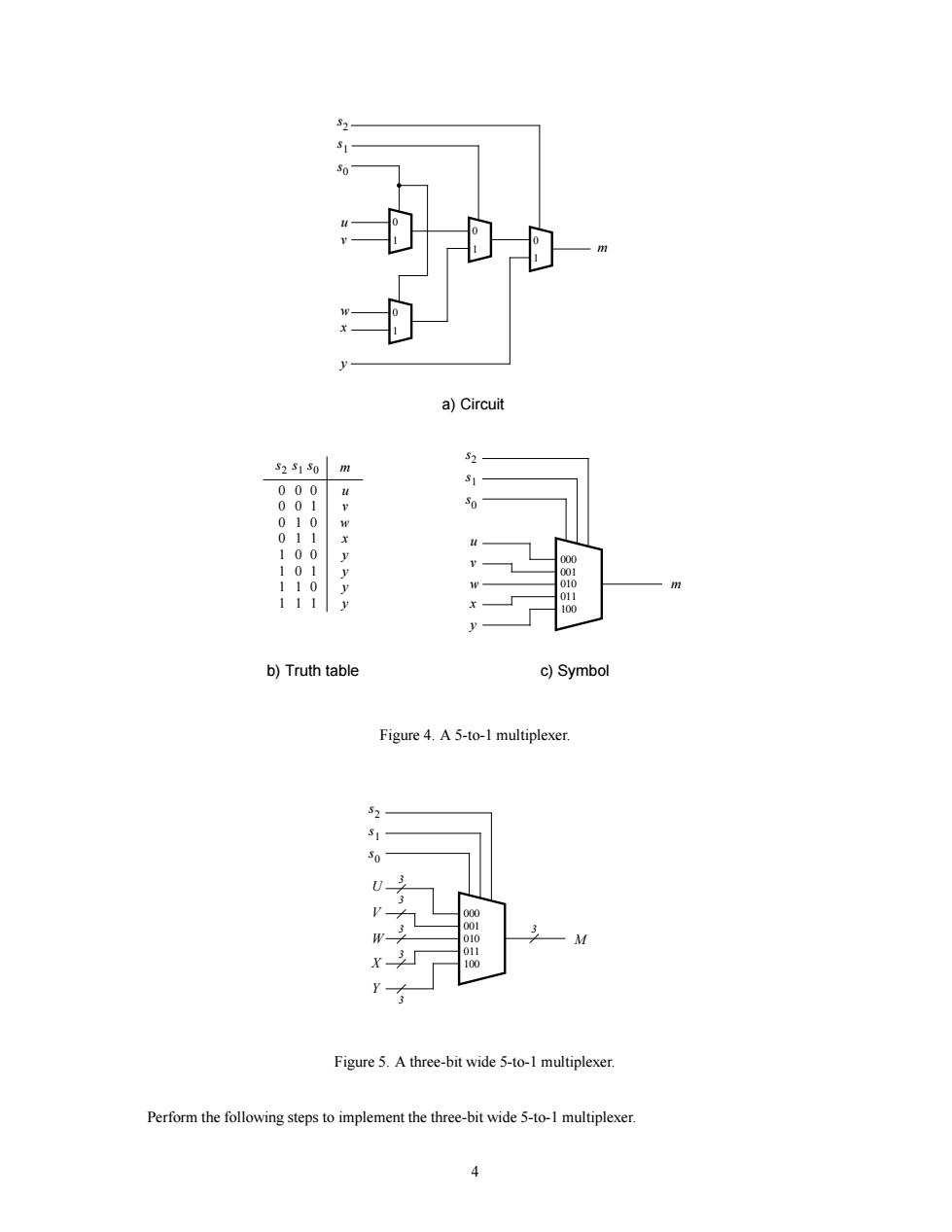
a)Circuit 32s150m 拍出 b)Truth table c)Symbol Figure 4.A 5-to-1 multiplexer Figure 5.A three-bit wide 5-to-1 multiplexer Perform the following steps to implement the three-bit wide 5-to-1 multiplexer.0 1 a) Circuit 0 1 0 1 w x v u 000 m 0 1 s1 s2 s0 y m 001 010 011 100 s1 s2 s0 w x v u y c) Symbol m 0 0 u v b) Truth table s1 s0 s2 0 0 0 1 0 0 w x 1 0 1 1 1 0 0 y 1 1 0 1 1 0 111 y y y Figure 4. A 5-to-1 multiplexer. 000 M 001 010 011 100 s1 s2 s0 W X V U Y 3 3 3 3 3 3 Figure 5. A three-bit wide 5-to-1 multiplexer. Perform the following steps to implement the three-bit wide 5-to-1 multiplexer. 4