正在加载图片...

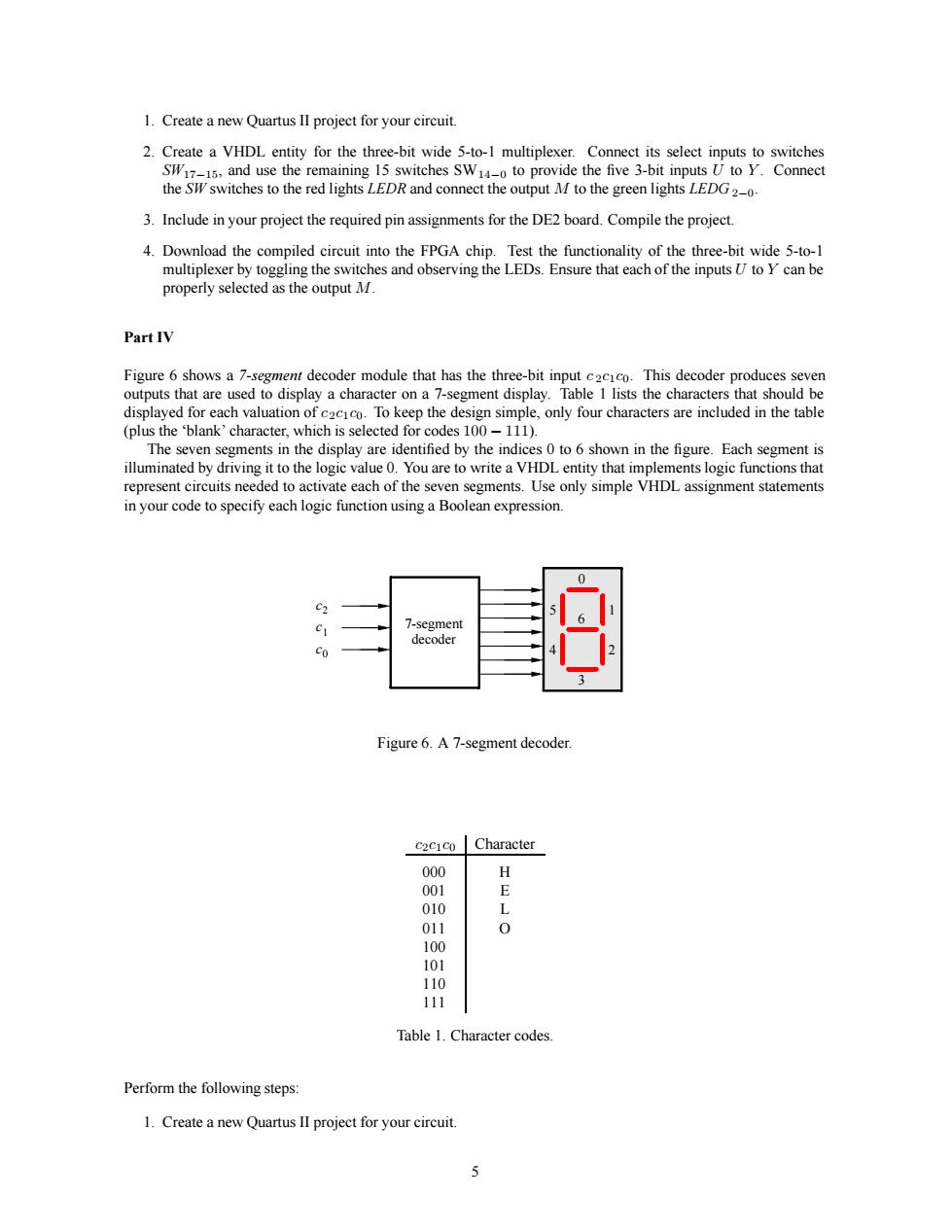
1.Create a new Quartus ll project for your circuit. the Sswitches to the red lights LEDR and connect the output M to the green lightsLEDG 3.Include in your project the required pin assignments for the DE2 board.Compile the project. 4.Download the compiled circuit into the FPGA chip.Test the functionality of the three-bit wide 5-to- es and observing the LEDs.Ensure that each of the inputs U to Y can be outpu PartIV .This decoder producess To kena the d (plus theblank'character,which is selected for codes100-111). esegments in the display are identifed by the ind to o shown in the figure.Each segment s riving it to the logie va moLrcodciospecifCaehi1ogicfincionLsigaBolcanec nression Figure6.A7-segment decoder cacico Character 000 001 Table 1.Character codes. Perform the following steps: 1.Create a new Quartus lI project for your circuit. 1. Create a new Quartus II project for your circuit. 2. Create a VHDL entity for the three-bit wide 5-to-1 multiplexer. Connect its select inputs to switches SW17−15, and use the remaining 15 switches SW14−0 to provide the five 3-bit inputs U to Y . Connect the SW switches to the red lights LEDR and connect the output M to the green lights LEDG 2−0. 3. Include in your project the required pin assignments for the DE2 board. Compile the project. 4. Download the compiled circuit into the FPGA chip. Test the functionality of the three-bit wide 5-to-1 multiplexer by toggling the switches and observing the LEDs. Ensure that each of the inputs U to Y can be properly selected as the output M. Part IV Figure 6 shows a 7-segment decoder module that has the three-bit input c 2c1c0. This decoder produces seven outputs that are used to display a character on a 7-segment display. Table 1 lists the characters that should be displayed for each valuation of c2c1c0. To keep the design simple, only four characters are included in the table (plus the ‘blank’ character, which is selected for codes 100 − 111). The seven segments in the display are identified by the indices 0 to 6 shown in the figure. Each segment is illuminated by driving it to the logic value 0. You are to write a VHDL entity that implements logic functions that represent circuits needed to activate each of the seven segments. Use only simple VHDL assignment statements in your code to specify each logic function using a Boolean expression. 7-segment 0 1 2 3 4 5 6 decoder c2 c1 c0 Figure 6. A 7-segment decoder. c2c1c0 Character 000 H 001 E 010 L 011 O 100 101 110 111 Table 1. Character codes. Perform the following steps: 1. Create a new Quartus II project for your circuit. 5