正在加载图片...
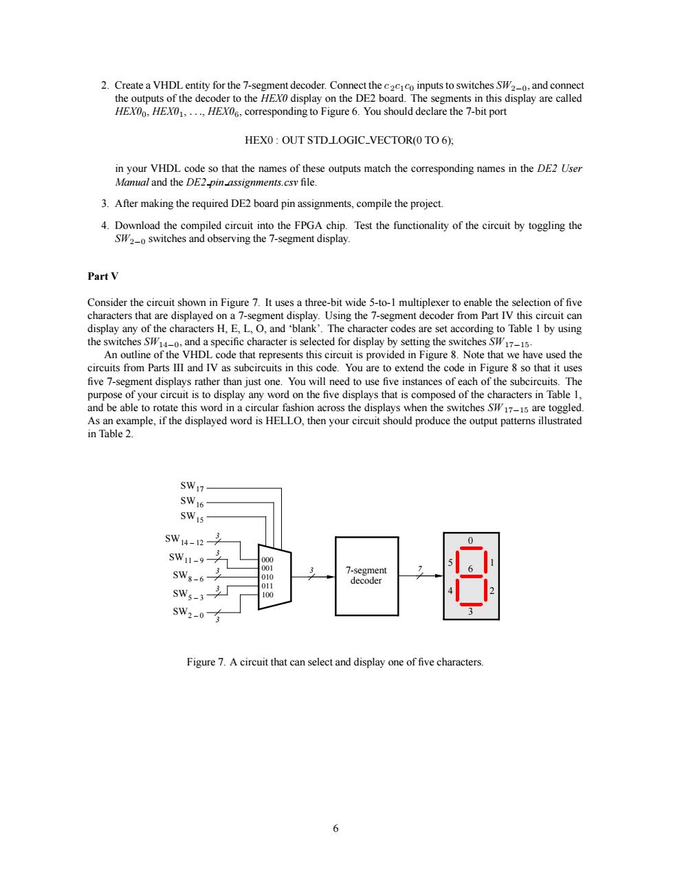
corresponding to Figure 6.You should declare the 7-bit port HEXO:OUT STDLOGIC_VECTOR(O TO 6): in your VHDL code so that the names of these outputs match the corresponding names in the DE2 User Manal and the DE2-pin-assignments.csv file. 3.After making the required DE2 board pin assignments,compile the project Test the functionality of the circuit by toggling the PartV Consider the circuit shown in Figure 7.It uses a three-bit wide 5-to-1 multiplexer to enable the selection of five characters that are displayed egmen e cn nd s H.EL et a I by using uinhe VHDLthatprethi circut sprovided FreNotethathave ue the circuits from Parts Il and IV as subcircuits in this code.You are to extend the code in Figureso that it uses five 7-segment displays rathe than just one will ne to use live instances o are too Asan example,if the displayed word is HELLO,then your circuit should produce the output pattems ilustrated in Table 2. SW17- SWm1-9 SW。 sws-3 sw2-0有 Figure 7.Acircuit that can select and display one of five characters 62. Create a VHDL entity for the 7-segment decoder. Connect the c 2c1c0 inputs to switches SW2−0, and connect the outputs of the decoder to the HEX0 display on the DE2 board. The segments in this display are called HEX00, HEX01, ..., HEX06, corresponding to Figure 6. You should declare the 7-bit port HEX0 : OUT STD LOGIC VECTOR(0 TO 6); in your VHDL code so that the names of these outputs match the corresponding names in the DE2 User Manual and the DE2 pin assignments.csv file. 3. After making the required DE2 board pin assignments, compile the project. 4. Download the compiled circuit into the FPGA chip. Test the functionality of the circuit by toggling the SW2−0 switches and observing the 7-segment display. Part V Consider the circuit shown in Figure 7. It uses a three-bit wide 5-to-1 multiplexer to enable the selection of five characters that are displayed on a 7-segment display. Using the 7-segment decoder from Part IV this circuit can display any of the characters H, E, L, O, and ‘blank’. The character codes are set according to Table 1 by using the switches SW14−0, and a specific character is selected for display by setting the switches SW17−15. An outline of the VHDL code that represents this circuit is provided in Figure 8. Note that we have used the circuits from Parts III and IV as subcircuits in this code. You are to extend the code in Figure 8 so that it uses five 7-segment displays rather than just one. You will need to use five instances of each of the subcircuits. The purpose of your circuit is to display any word on the five displays that is composed of the characters in Table 1, and be able to rotate this word in a circular fashion across the displays when the switches SW 17−15 are toggled. As an example, if the displayed word is HELLO, then your circuit should produce the output patterns illustrated in Table 2. 7-segment decoder 000 001 010 011 100 3 3 3 3 3 3 SW17 SW16 SW15 SW14 12 – SW11 9 – SW8 6 – SW5 3 – SW2 0 – 7 0 1 2 3 4 5 6 Figure 7. A circuit that can select and display one of five characters. 6