正在加载图片...
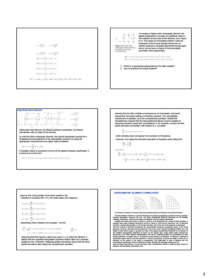
815. -gg n=+- 图n=1+r1卡到 o d vnatie Nannei-rt as is )Cnre间a 古 之--a+-= wcoy 南=南+生=+0 =合+生由合+C 4=,地山=+C 4 4 To develop a higher-order rectangular element, the logical progression is to place an additional node at the midpoint of each side of the element, as in Figure 6.15. This poses an immediate problem, however. Inspection of the Pascal triangle shows that we cannot construct a complete polynomial having eight terms, but we have a choice of two incomplete, symmetric cubic polynomials: 1. Which is a appropriate polynomial form for field variable? 2. how to construct the shape function? Eight-node brick element: (a) Global Cartesian coordinates. (b) Natural coordinates with an origin at the centroid. As with the plane rectangular element, the natural coordinates provide for a straightforward development of the interpolation functions by using the appropriate monomial terms to satisfy nodal conditions. If Equation above is expressed in terms of the global Cartesian coordinates, it is found to be of the form Eight-Node Brick Element showing that the field variable is expressed as an incomplete, symmetric polynomial. Geometric isotropy is therefore assured. The compatibility requirement is satisfied, as is the completeness condition. Recall that completeness requires that the first partial derivatives must be capable of assuming constant values (for C0 problems). If, for example, we take the first partial derivative of Equation with respect to x, we obtain which certainly does not appear to be constant at first glance. However, if we apply the derivative operation to Equation while noting that observe that, if the gradient of the field variable in the x direction is constant, ∂/∂ x = C, the nodal values are related by Substituting these relations into Equation , we find Observing that this result is valid at any point (r, s, t) within the element, it follows that the specified interpolation functions indeed allow for a constant gradient in the x direction. Following similar procedures shows that the other partial derivatives also satisfy the completeness condition. ISOPARAMETRIC (ELEMENT) FORMULATION (a) A domain to be modeled. (b) Triangular elements.(c) Rectangular elements. (d) Rectangular and quadrilateral elements. The finite element method is a powerful technique for analyzing engineering problems involving complex, irregular geometries. However, the two- and three dimensional elements discussed so far (triangle, rectangle, tetrahedron, brick) cannot always be efficiently used for irregular geometries. Consider the plane area shown in Figure a, which is to be discretized via a mesh of finite elements. A possible mesh using triangular elements is shown in Figure b. Note that the outermost “row” of elements provides a chordal approximation to the circular boundary, and as the size of the elements is decreased (and the number of elements increased), the approximation becomes increasingly closer to the actual geometry. However, also note that the elements in the inner “rows” become increasingly slender (i.e., the height to base ratio is large). In general, the ratio of the largest characteristic dimension of an element to the smallest characteristic dimension is known as the aspect ratio. Large aspect ratios increase the inaccuracy of the finite element representation and have a detrimental effect on convergence of finite element solutions. An aspect ratio of 1 is ideal but cannot always be maintained. In Figure b, to maintain a reasonable aspect ratio for the inner elements, it would be necessary to reduce the height of each row of elements as the center of the sector is approached. This observation is also in keeping with the convergence requirements of the h-refinement method. Although the triangular element can be used to closely approximate a curved boundary, other considerations dictate a relatively large number of elements and associated computation time