FEM-Chapter6 COMPATIBILITY AND COMPLETENESS REQUIREMENTS he n ducng indvidud elemen s) ged.the o c ete:"p =∑Ns8 Nature of Finite Element Solutions nacal model of the real structure,based on man (b) umber of noses (points).thus Compatblity or beam element=k=a答g山anl4 rdondre a o st derv eheedvanablebmmn 1
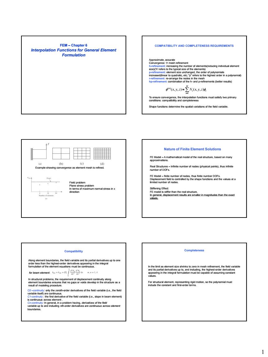
1 FEM – Chapter 6 Interpolation Functions for General Element Formulation COMPATIBILITY AND COMPLETENESS REQUIREMENTS Approximate, accurate Convergence mesh refinement h-refinement: increasing the number of elements(reducing individual element size)(‘h’ refers to the typical size of the elements) p-refinement: element size unchanged, the order of polynomials increased(linear to quadratic, etc; “p” refers to the highest order in a polynomial) r-refinement: re-arrange the nodes in the mesh hp-refinement: combination of the h- and p-refinements (better results) M i i i e x y z N x y z 1 ( ) ( , , ) ( , , ) To ensure convergence, the interpolation functions must satisfy two primary conditions: compatibility and completeness Shape functions determine the spatial variations of the field variable. Field problem Plane stress problem In terms of maximum normal stress in x direction Example showing convergence as element mesh is refined. Nature of Finite Element Solutions FE Model – A mathematical model of the real structure, based on many approximations. Real Structures – Infinite number of nodes (physical points), thus infinite number of DOFs. FE Model – finite number of nodes, thus finite number DOFs. Displacement field is controlled by the shape functions and the values at a limited number of nodes. Stiffening Effect: FE model is stiffer than the real structure. In general, displacement results are smaller in magnitudes than the exact values. Compatibility Along element boundaries, the field variable and its partial derivatives up to one order less than the highest-order derivatives appearing in the integral formulation of the element equations must be continuous. for beam element: In structural problems, the requirement of displacement continuity along element boundaries ensures that no gaps or voids develop in the structure as a result of modeling procedure. C0 –continuity: only the zeroth-order derivatives of the field variable (i.e., the field variable itself) are continuous. C1-continuity : the first derivative of the field variable (i.e., slope in beam element) is continuous across element . Cn-continuity: In general, in a problem having, derivatives of the field variable up to and including nth-order derivatives are continuous across element boundaries. Completeness In the limit as element size shrinks to zero in mesh refinement, the field variable and its partial derivatives up to, and including, the highest-order derivatives appearing in the integral formulation must be capable of assuming constant values. For structural element, representing rigid motion, so the polynomial must include the constant and first-order terms
alceoddbeastoramenshahg7noder a-儿k Σx 长-N,4-N化的-) Higher-Order One-Dimmensional Elements (Lagrange Interpolation ) ybe马(gn由p内am -0 ,( 2
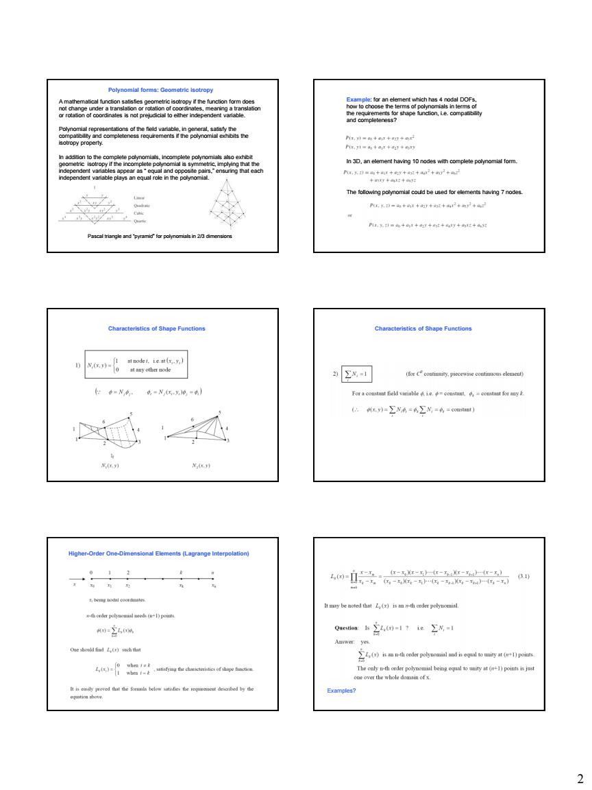
2 Polynomial forms: Geometric isotropy A mathematical function satisfies geometric isotropy if the function form does not change under a translation or rotation of coordinates, meaning a translation or rotation of coordinates is not prejudicial to either independent variable. Polynomial representations of the field variable, in general, satisfy the compatibility and completeness requirements if the polynomial exhibits the isotropy property. In addition to the complete polynomials, incomplete polynomials also exhibit geometric isotropy if the incomplete polynomial is symmetric, implying that the independent variables appear as “ equal and opposite pairs,” ensuring that each independent variable plays an equal role in the polynomial. Pascal triangle and “pyramid” for polynomials in 2/3 dimensions Example: for an element which has 4 nodal DOFs, how to choose the terms of polynomials in terms of the requirements for shape function, i.e. compatibility and completeness? In 3D, an element having 10 nodes with complete polynomial form. The following polynomial could be used for elements having 7 nodes. Characteristics of Shape Functions Characteristics of Shape Functions Higher-Order One-Dimensional Elements (Lagrange Interpolation) Examples?
肉黑功=偶+r+妈5 △公A (a) (b) 阁 倒3 nddee间6 ode业同i0oese =女b-+-n+n- Area Coordina 套誉 Li+L+L= Mn-与-h+-约+对-时 A 北剑 ix-Node Triangular Element 卧:目 -(L- 月-可目 -(-)-- 自
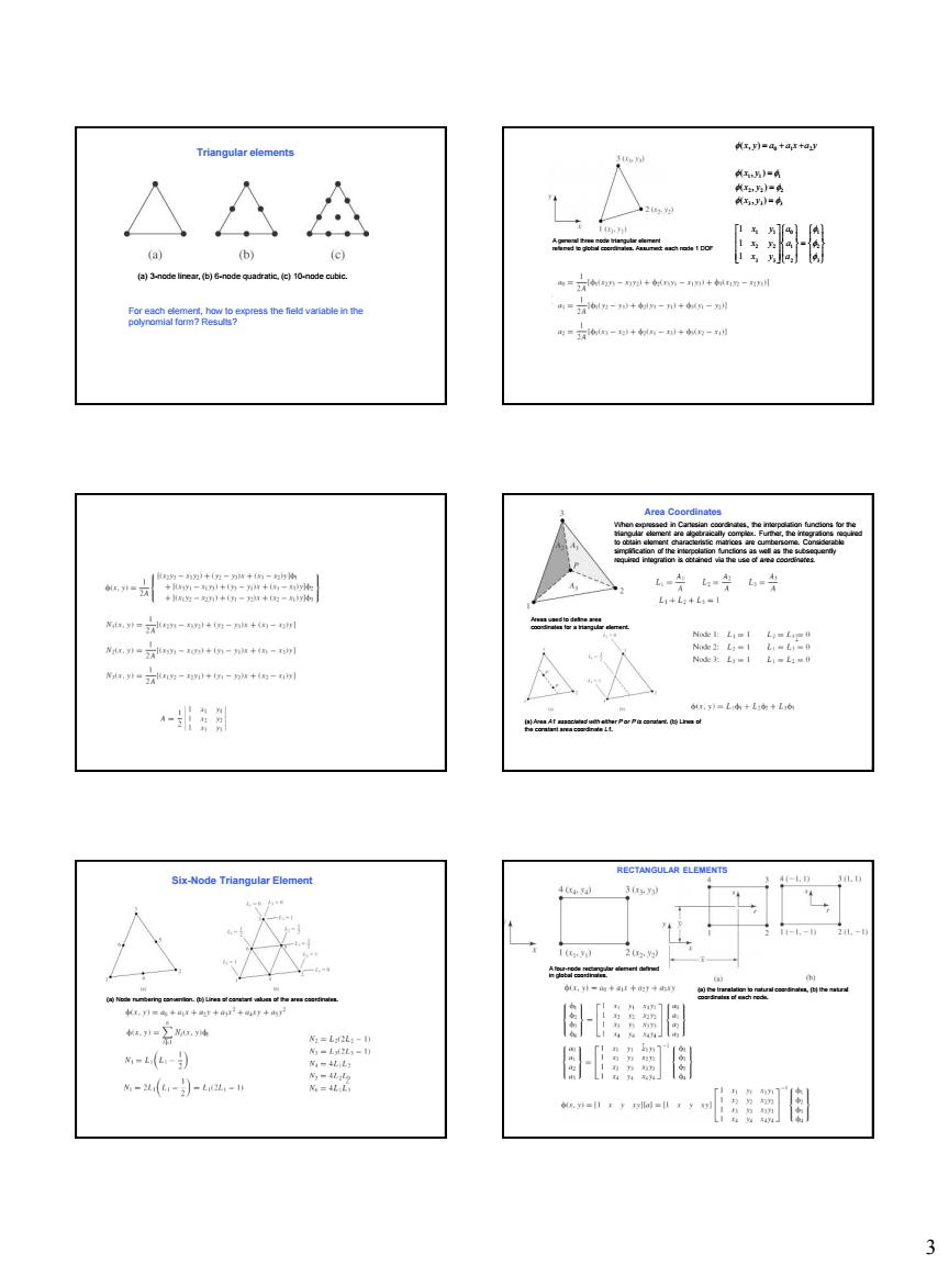
3 Triangular elements For each element, how to express the field variable in the polynomial form? Results? (a) 3-node linear, (b) 6-node quadratic, (c) 10-node cubic. A general three node triangular element referred to global coordinates. Assumed: each node 1 DOF 3 2 1 2 1 0 3 3 2 2 1 1 3 3 3 2 2 2 1 1 1 0 1 2 1 1 1 ( , ) ( , ) ( , ) ( , ) a a a x y x y x y x y x y x y x y a a x a y Area Coordinates Areas used to define area coordinates for a triangular element. (a) Area A1 associated with either P or P is constant. (b) Lines of the constant area coordinate L1. When expressed in Cartesian coordinates, the interpolation functions for the triangular element are algebraically complex. Further, the integrations required to obtain element characteristic matrices are cumbersome. Considerable simplification of the interpolation functions as well as the subsequently required integration is obtained via the use of area coordinates. Six-Node Triangular Element (a) Node numbering convention. (b) Lines of constant values of the area coordinates. RECTANGULAR ELEMENTS (a) the translation to natural coordinates, (b) the natural coordinates of each node. A four-node rectangular element defined in global coordinates
815. -gg n=+- 图n=1+r1卡到 o d vnatie Nannei-rt as is )Cnre间a 古 之--a+-= wcoy 南=南+生=+0 =合+生由合+C 4=,地山=+C 4
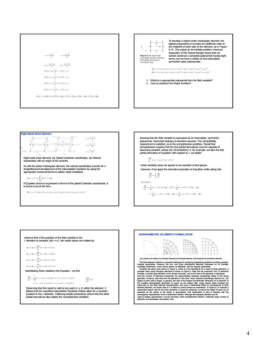
4 To develop a higher-order rectangular element, the logical progression is to place an additional node at the midpoint of each side of the element, as in Figure 6.15. This poses an immediate problem, however. Inspection of the Pascal triangle shows that we cannot construct a complete polynomial having eight terms, but we have a choice of two incomplete, symmetric cubic polynomials: 1. Which is a appropriate polynomial form for field variable? 2. how to construct the shape function? Eight-node brick element: (a) Global Cartesian coordinates. (b) Natural coordinates with an origin at the centroid. As with the plane rectangular element, the natural coordinates provide for a straightforward development of the interpolation functions by using the appropriate monomial terms to satisfy nodal conditions. If Equation above is expressed in terms of the global Cartesian coordinates, it is found to be of the form Eight-Node Brick Element showing that the field variable is expressed as an incomplete, symmetric polynomial. Geometric isotropy is therefore assured. The compatibility requirement is satisfied, as is the completeness condition. Recall that completeness requires that the first partial derivatives must be capable of assuming constant values (for C0 problems). If, for example, we take the first partial derivative of Equation with respect to x, we obtain which certainly does not appear to be constant at first glance. However, if we apply the derivative operation to Equation while noting that observe that, if the gradient of the field variable in the x direction is constant, ∂/∂ x = C, the nodal values are related by Substituting these relations into Equation , we find Observing that this result is valid at any point (r, s, t) within the element, it follows that the specified interpolation functions indeed allow for a constant gradient in the x direction. Following similar procedures shows that the other partial derivatives also satisfy the completeness condition. ISOPARAMETRIC (ELEMENT) FORMULATION (a) A domain to be modeled. (b) Triangular elements.(c) Rectangular elements. (d) Rectangular and quadrilateral elements. The finite element method is a powerful technique for analyzing engineering problems involving complex, irregular geometries. However, the two- and three dimensional elements discussed so far (triangle, rectangle, tetrahedron, brick) cannot always be efficiently used for irregular geometries. Consider the plane area shown in Figure a, which is to be discretized via a mesh of finite elements. A possible mesh using triangular elements is shown in Figure b. Note that the outermost “row” of elements provides a chordal approximation to the circular boundary, and as the size of the elements is decreased (and the number of elements increased), the approximation becomes increasingly closer to the actual geometry. However, also note that the elements in the inner “rows” become increasingly slender (i.e., the height to base ratio is large). In general, the ratio of the largest characteristic dimension of an element to the smallest characteristic dimension is known as the aspect ratio. Large aspect ratios increase the inaccuracy of the finite element representation and have a detrimental effect on convergence of finite element solutions. An aspect ratio of 1 is ideal but cannot always be maintained. In Figure b, to maintain a reasonable aspect ratio for the inner elements, it would be necessary to reduce the height of each row of elements as the center of the sector is approached. This observation is also in keeping with the convergence requirements of the h-refinement method. Although the triangular element can be used to closely approximate a curved boundary, other considerations dictate a relatively large number of elements and associated computation time

兰器装 二 留- ★》--之Nm D if F-NI D h2-Dcme -∑V%,,-∑N
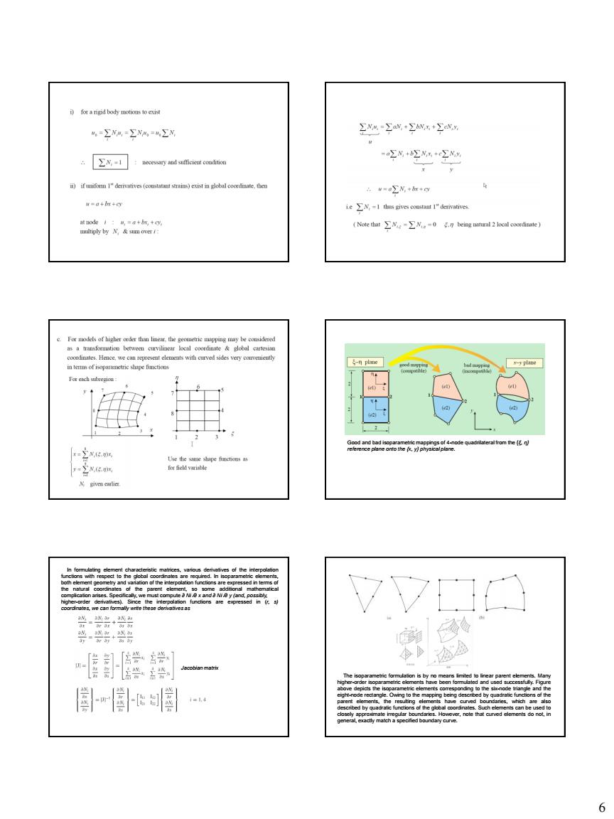
5 If we consider rectangular elements as in Figure c (an intentionally crude mesh for illustrative purposes), the problems are apparent. Unless the elements are very small, the area of the domain excluded from the model (the shaded area in the figure) may be significant. For the case depicted, a large number of very small square elements best approximates the geometry. At this point, you may think, Why not use triangular and rectangular elements in the same mesh to improve the model? Indeed, a combination of the element types can be used to improve the geometric accuracy of the model. The shaded areas of Figure c could be modeled by three-node triangular elements. Such combination of element types may not be the best in terms of solution accuracy since the rectangular element and the triangular element have, by necessity, different order polynomial representations of the field variable. The field variable is continuous across such element boundaries; this is guaranteed by the finite element formulation. However, conditions on derivatives of the field variable for the two element types are quite different. On a curved boundary such as that shown, the triangular element used to fill the “gaps” left by the rectangular elements may also have adverse aspect ratio characteristics. Now examine Figure d, which shows the same area meshed with rectangular elements and a new element applied near the periphery of the domain. The new element has four nodes, straight sides, but is not rectangular. (Please note that the mesh shown is intentionally coarse for purposes of illustration.) The new element is known as a general two-dimensional quadrilateral element and is seen to mesh ideally with the rectangular element as well as approximate the curved boundary, just like the triangular element. The four-node quadrilateral element is derived from the four-node rectangular element (known as the parent element) element via a mapping process. Figure above shows the parent element and its natural (r, s) coordinates and the quadrilateral element in a global Cartesian coordinate system. The geometry of the quadrilateral element is described by Mapping of a parent element into an isoparametric element. where the Gi (x , y) can be considered as geometric interpolation functions, and each such function is associated with a particular node of the quadrilateral element. Given the geometry and the form of Equations above, each function Gi (x , y) must evaluate to unity at its associated node and to zero at each of the other three nodes. These conditions are exactly the same as those imposed on the interpolation functions of the parent element. Consequently, the interpolation functions for the parent element can be used for the geometric functions, if we map the coordinates so that Consequently, the geometric expressions become Clearly, we can also express the field variable variation in the quadrilateral element as Since the same interpolation functions are used for both the field variable and description of element geometry, the procedure is known as isoparametric (constant parameter) mapping. The element defined by such a procedure is known as an isoparametric element
4=∑V%-∑州%=ΣN 2g Σ:y 空N+空+字 元-∑N++g =g+然g X 蜜I 数r VVDO 卸像一 凰骨目国… 影 6
6 Good and bad isoparametric mappings of 4-node quadrilateral from the {ξ, η} reference plane onto the {x, y} physical plane. In formulating element characteristic matrices, various derivatives of the interpolation functions with respect to the global coordinates are required. In isoparametric elements, both element geometry and variation of the interpolation functions are expressed in terms of the natural coordinates of the parent element, so some additional mathematical complication arises. Specifically, we must compute ∂ Ni /∂ x and ∂ Ni /∂ y (and, possibly, higher-order derivatives). Since the interpolation functions are expressed in (r, s) coordinates, we can formally write these derivatives as Jacobian matrix The isoparametric formulation is by no means limited to linear parent elements. Many higher-order isoparametric elements have been formulated and used successfully. Figure above depicts the isoparametric elements corresponding to the six-node triangle and the eight-node rectangle. Owing to the mapping being described by quadratic functions of the parent elements, the resulting elements have curved boundaries, which are also described by quadratic functions of the global coordinates. Such elements can be used to closely approximate irregular boundaries. However, note that curved elements do not, in general, exactly match a specified boundary curve

CONCLUSIONS As the
7 •Same shape functions are used to interpolate nodal coordinates and displacements •Shape functions are defined for an idealized mapped element (e.g. square for any quadrilateral element) •Advantages include more flexible shapes and compatibility •We pay the price in complexity and require numerical integration to calculate stiffness matrices and equivalent loads The developments presented in this chapter show how interpolation functions for one-, two-, and three-dimensional elements can be obtained via a systematic procedure. Also, the algebraically tedious procedure can often be bypassed using intuition and logic when natural coordinates are used. The interpolation functions discussed are standard polynomial forms but by no means exhaustive of the interpolation functions that have been developed for use in finite element analysis. As the objective of this text is to present the fundamentals of finite element analysis, the material of this chapter is intended to cover the basic concepts of interpolation functions without proposing to be comprehensive. The treatment here is intended to form a basis for formulation of finite element models of various physical problems in following chapters. In general, every element and the associated interpolation functions discussed here can be applied to specific problems, as is illustrated in the remainder of the text. CONCLUSIONS