正在加载图片...

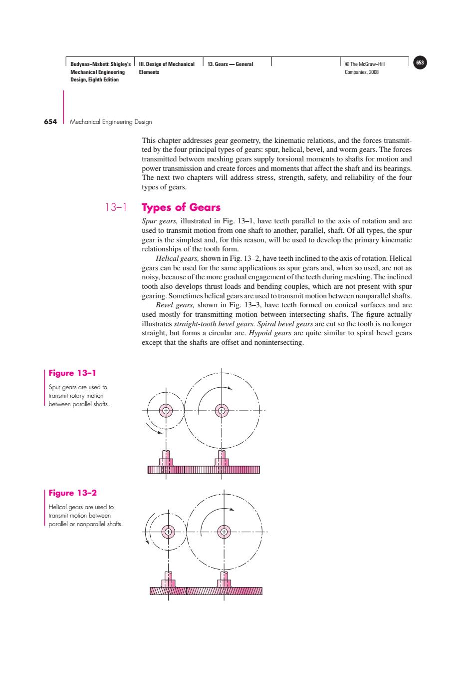
Budynas-Nisbett:Shigley's Ill.Design of Mechanical 13.Gears-General T©The McGraw-Hill 653 Mechanical Engineering Elements Companies,2008 Design,Eighth Edition 654 Mechanical Engineering Design This chapter addresses gear geometry,the kinematic relations,and the forces transmit- ted by the four principal types of gears:spur,helical,bevel,and worm gears.The forces transmitted between meshing gears supply torsional moments to shafts for motion and power transmission and create forces and moments that affect the shaft and its bearings. The next two chapters will address stress,strength,safety,and reliability of the four types of gears. 13-1 Types of Gears Spur gears,illustrated in Fig.13-1,have teeth parallel to the axis of rotation and are used to transmit motion from one shaft to another,parallel,shaft.Of all types,the spur gear is the simplest and,for this reason,will be used to develop the primary kinematic relationships of the tooth form. Helical gears,shown in Fig.13-2,have teeth inclined to the axis of rotation.Helical gears can be used for the same applications as spur gears and,when so used,are not as noisy,because of the more gradual engagement of the teeth during meshing.The inclined tooth also develops thrust loads and bending couples.which are not present with spur gearing.Sometimes helical gears are used to transmit motion between nonparallel shafts. Bevel gears,shown in Fig.13-3,have teeth formed on conical surfaces and are used mostly for transmitting motion between intersecting shafts.The figure actually illustrates straight-tooth bevel gears.Spiral bevel gears are cut so the tooth is no longer straight,but forms a circular arc.Hypoid gears are quite similar to spiral bevel gears except that the shafts are offset and nonintersecting. Figure 13-1 Spur gears are used to transmit rotary motion between parallel shafts. IⅧ Figure 13-2 Helical gears are used to transmit motion between parallel or nonparallel shafts.Budynas−Nisbett: Shigley’s Mechanical Engineering Design, Eighth Edition III. Design of Mechanical Elements 13. Gears — General © The McGraw−Hill 653 Companies, 2008 654 Mechanical Engineering Design Figure 13–1 Spur gears are used to transmit rotary motion between parallel shafts. Figure 13–2 Helical gears are used to transmit motion between parallel or nonparallel shafts. This chapter addresses gear geometry, the kinematic relations, and the forces transmitted by the four principal types of gears: spur, helical, bevel, and worm gears. The forces transmitted between meshing gears supply torsional moments to shafts for motion and power transmission and create forces and moments that affect the shaft and its bearings. The next two chapters will address stress, strength, safety, and reliability of the four types of gears. 13–1 Types of Gears Spur gears, illustrated in Fig. 13–1, have teeth parallel to the axis of rotation and are used to transmit motion from one shaft to another, parallel, shaft. Of all types, the spur gear is the simplest and, for this reason, will be used to develop the primary kinematic relationships of the tooth form. Helical gears,shown in Fig. 13–2, have teeth inclined to the axis of rotation. Helical gears can be used for the same applications as spur gears and, when so used, are not as noisy, because of the more gradual engagement of the teeth during meshing. The inclined tooth also develops thrust loads and bending couples, which are not present with spur gearing. Sometimes helical gears are used to transmit motion between nonparallel shafts. Bevel gears, shown in Fig. 13–3, have teeth formed on conical surfaces and are used mostly for transmitting motion between intersecting shafts. The figure actually illustrates straight-tooth bevel gears. Spiral bevel gears are cut so the tooth is no longer straight, but forms a circular arc. Hypoid gears are quite similar to spiral bevel gears except that the shafts are offset and nonintersecting