正在加载图片...
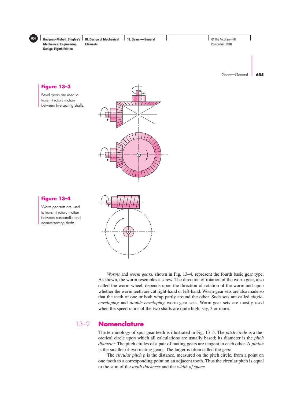
654 Budynas-Nisbett:Shigley's Ill.Design of Mechanical 13.Gears-General T©The McGraw-Hil Mechanical Engineering Elements Companies,2008 Design,Eighth Edition Gears-General 655 Figure 13-3 Bevel gears are used to transmit rotary motion between intersecting shafts. Figure 13-4 Worm gearsets are used to transmit rotary motion between nonparallel and nonintersecting shafts. Worms and worm gears,shown in Fig.13-4,represent the fourth basic gear type. As shown,the worm resembles a screw.The direction of rotation of the worm gear,also called the worm wheel,depends upon the direction of rotation of the worm and upon whether the worm teeth are cut right-hand or left-hand.Worm-gear sets are also made so that the teeth of one or both wrap partly around the other.Such sets are called single- enveloping and double-enveloping worm-gear sets.Worm-gear sets are mostly used when the speed ratios of the two shafts are quite high,say,3 or more. 13-2 Nomenclature The terminology of spur-gear teeth is illustrated in Fig.13-5.The pitch circle is a the- oretical circle upon which all calculations are usually based;its diameter is the pitch diameter.The pitch circles of a pair of mating gears are tangent to each other.A pinion is the smaller of two mating gears.The larger is often called the gear. The circular pitch p is the distance,measured on the pitch circle,from a point on one tooth to a corresponding point on an adjacent tooth.Thus the circular pitch is equal to the sum of the tooth thickness and the width of space.Budynas−Nisbett: Shigley’s Mechanical Engineering Design, Eighth Edition III. Design of Mechanical Elements 13. Gears — General 654 © The McGraw−Hill Companies, 2008 Gears—General 655 Figure 13–3 Bevel gears are used to transmit rotary motion between intersecting shafts. Worms and worm gears, shown in Fig. 13–4, represent the fourth basic gear type. As shown, the worm resembles a screw. The direction of rotation of the worm gear, also called the worm wheel, depends upon the direction of rotation of the worm and upon whether the worm teeth are cut right-hand or left-hand. Worm-gear sets are also made so that the teeth of one or both wrap partly around the other. Such sets are called singleenveloping and double-enveloping worm-gear sets. Worm-gear sets are mostly used when the speed ratios of the two shafts are quite high, say, 3 or more. 13–2 Nomenclature The terminology of spur-gear teeth is illustrated in Fig. 13–5. The pitch circle is a theoretical circle upon which all calculations are usually based; its diameter is the pitch diameter. The pitch circles of a pair of mating gears are tangent to each other. A pinion is the smaller of two mating gears. The larger is often called the gear. The circular pitch p is the distance, measured on the pitch circle, from a point on one tooth to a corresponding point on an adjacent tooth. Thus the circular pitch is equal to the sum of the tooth thickness and the width of space. Figure 13–4 Worm gearsets are used to transmit rotary motion between nonparallel and nonintersecting shafts