正在加载图片...

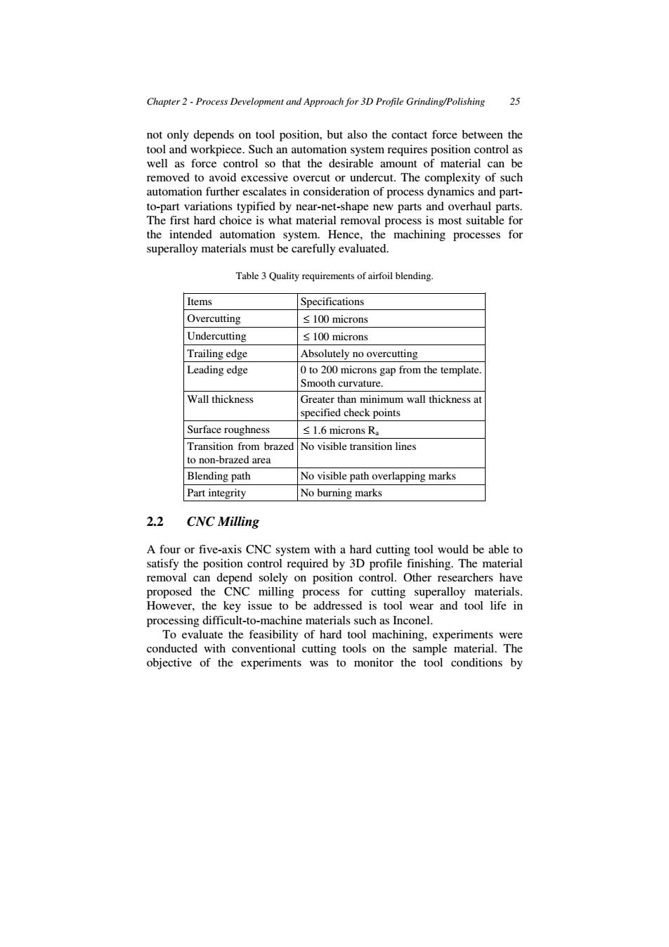
Chapter 2-Process Development and Approach for 3D Profile Grinding/Polishing 25 not only depends on tool position,but also the contact force between the tool and workpiece.Such an automation system requires position control as well as force control so that the desirable amount of material can be removed to avoid excessive overcut or undercut.The complexity of such automation further escalates in consideration of process dynamics and part- to-part variations typified by near-net-shape new parts and overhaul parts. The first hard choice is what material removal process is most suitable for the intended automation system.Hence,the machining processes for superalloy materials must be carefully evaluated. Table 3 Quality requirements of airfoil blending. Items Specifications Overcutting ≤100 microns Undercutting ≤100 microns Trailing edge Absolutely no overcutting Leading edge 0 to 200 microns gap from the template. Smooth curvature. Wall thickness Greater than minimum wall thickness at specified check points Surface roughness ≤1.6 microns Ra Transition from brazed No visible transition lines to non-brazed area Blending path No visible path overlapping marks Part integrity No burning marks 2.2 CNC Milling A four or five-axis CNC system with a hard cutting tool would be able to satisfy the position control required by 3D profile finishing.The material removal can depend solely on position control.Other researchers have proposed the CNC milling process for cutting superalloy materials. However,the key issue to be addressed is tool wear and tool life in processing difficult-to-machine materials such as Inconel. To evaluate the feasibility of hard tool machining,experiments were conducted with conventional cutting tools on the sample material.The objective of the experiments was to monitor the tool conditions byChapter 2 - Process Development and Approach for 3D Profile Grinding/Polishing 25 not only depends on tool position, but also the contact force between the tool and workpiece. Such an automation system requires position control as well as force control so that the desirable amount of material can be removed to avoid excessive overcut or undercut. The complexity of such automation further escalates in consideration of process dynamics and partto-part variations typified by near-net-shape new parts and overhaul parts. The first hard choice is what material removal process is most suitable for the intended automation system. Hence, the machining processes for superalloy materials must be carefully evaluated. Table 3 Quality requirements of airfoil blending. Items Specifications Overcutting ≤ 100 microns Undercutting ≤ 100 microns Trailing edge Absolutely no overcutting Leading edge 0 to 200 microns gap from the template. Smooth curvature. Wall thickness Greater than minimum wall thickness at specified check points Surface roughness ≤ 1.6 microns Ra Transition from brazed to non-brazed area No visible transition lines Blending path No visible path overlapping marks Part integrity No burning marks 2.2 CNC Milling A four or five-axis CNC system with a hard cutting tool would be able to satisfy the position control required by 3D profile finishing. The material removal can depend solely on position control. Other researchers have proposed the CNC milling process for cutting superalloy materials. However, the key issue to be addressed is tool wear and tool life in processing difficult-to-machine materials such as Inconel. To evaluate the feasibility of hard tool machining, experiments were conducted with conventional cutting tools on the sample material. The objective of the experiments was to monitor the tool conditions by