正在加载图片...
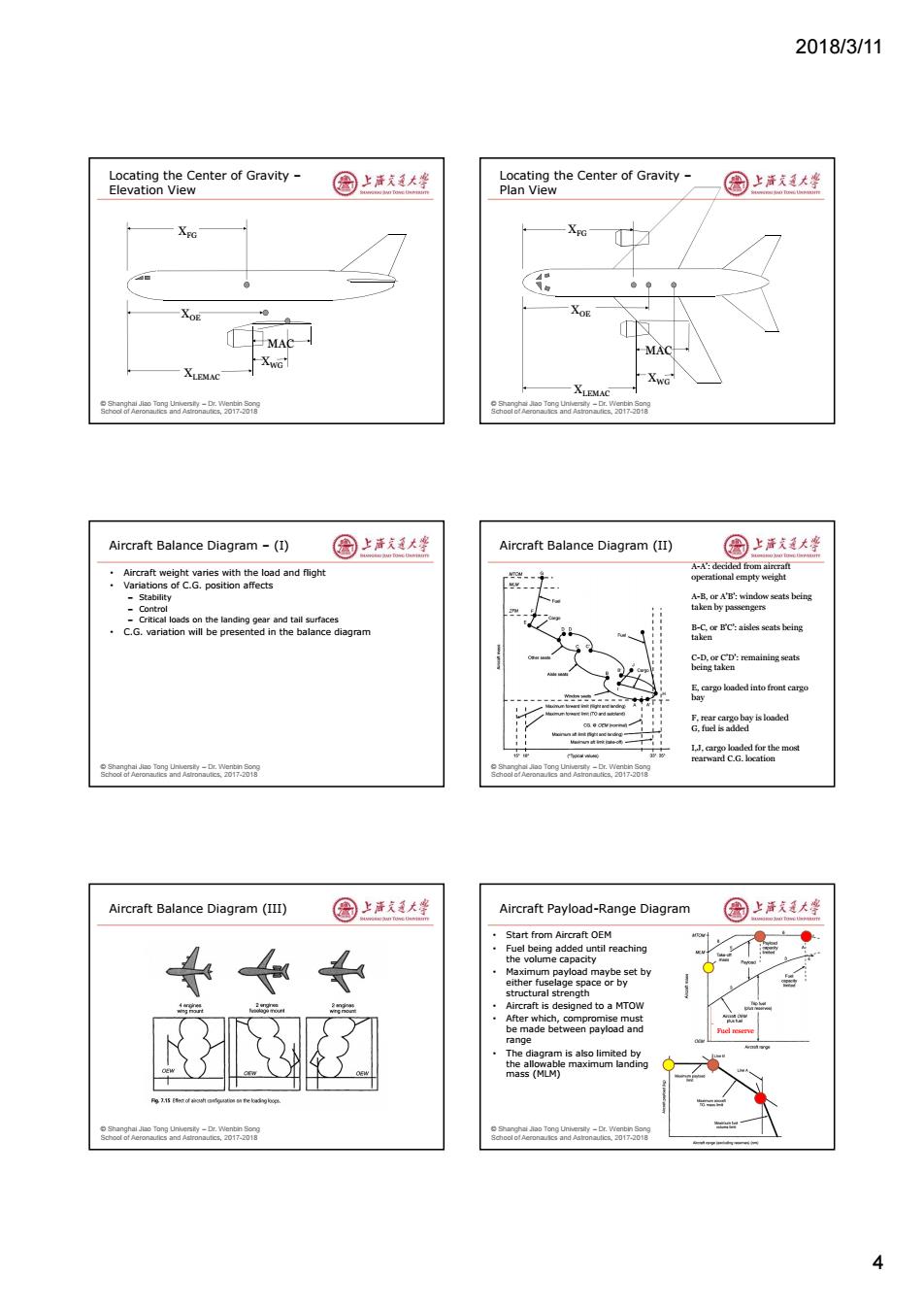
2018/3/11 Locating the Center of Gravity Elevation View 园上声充通大学 Locating the Center of Gravity- Plan View 国上清大峰 XEG XO ·MAC XWG XLEMAC XLEMAC r nd 7 Aircraft Balance Diagram -(I) 圆上活文大坐 Aircraft Balance Diagram (II) 圆上活大蜂 Aircraft weight varies with the load and flight Variations of C.G.position affects 、 A-A:decided froma operational empty weight Stability A-B.or A'B':window seats being the andn rand tall sua taken by passengers C.G.variation will be presented in the balance diagram B-C.or B'C':aisles seats being taken E,cargo loaded into front eargo bay I.J.cargo loaded for the most rearward C.G.location rAer Aircraft Balance Diagram (III) 圆上洋道大坐 Aircraft Payload-Range Diagram 国上洋大学 Start from Aircraft OEM Fuel being added until reaching the volume capacity Maximum payload maybe set by either fuselage space or by structural strength Aircraft is designed to a MTOW After which,compromise must be made between payload and range The diagram is also limited by the allowable maximum landing mass (MLM) 42018/3/11 4 © Shanghai Jiao Tong University – Dr. Wenbin Song School of Aeronautics and Astronautics, 2017-2018 XFG XOE XLEMAC MAC XWG Locating the Center of Gravity – Elevation View © Shanghai Jiao Tong University – Dr. Wenbin Song School of Aeronautics and Astronautics, 2017-2018 XFG XOE XLEMAC XWG MAC Locating the Center of Gravity – Plan View © Shanghai Jiao Tong University – Dr. Wenbin Song School of Aeronautics and Astronautics, 2017-2018 Aircraft Balance Diagram – (I) • Aircraft weight varies with the load and flight • Variations of C.G. position affects – Stability – Control – Critical loads on the landing gear and tail surfaces • C.G. variation will be presented in the balance diagram © Shanghai Jiao Tong University – Dr. Wenbin Song School of Aeronautics and Astronautics, 2017-2018 Aircraft Balance Diagram (II) A-A’: decided from aircraft operational empty weight A-B, or A’B’: window seats being taken by passengers B-C, or B’C’: aisles seats being taken C-D, or C’D’: remaining seats being taken E, cargo loaded into front cargo bay F, rear cargo bay is loaded G, fuel is added I,J, cargo loaded for the most rearward C.G. location © Shanghai Jiao Tong University – Dr. Wenbin Song School of Aeronautics and Astronautics, 2017-2018 Aircraft Balance Diagram (III) © Shanghai Jiao Tong University – Dr. Wenbin Song School of Aeronautics and Astronautics, 2017-2018 Aircraft Payload-Range Diagram • Start from Aircraft OEM • Fuel being added until reaching the volume capacity • Maximum payload maybe set by either fuselage space or by structural strength • Aircraft is designed to a MTOW • After which, compromise must be made between payload and range • The diagram is also limited by the allowable maximum landing mass (MLM) Fuel reserve