正在加载图片...

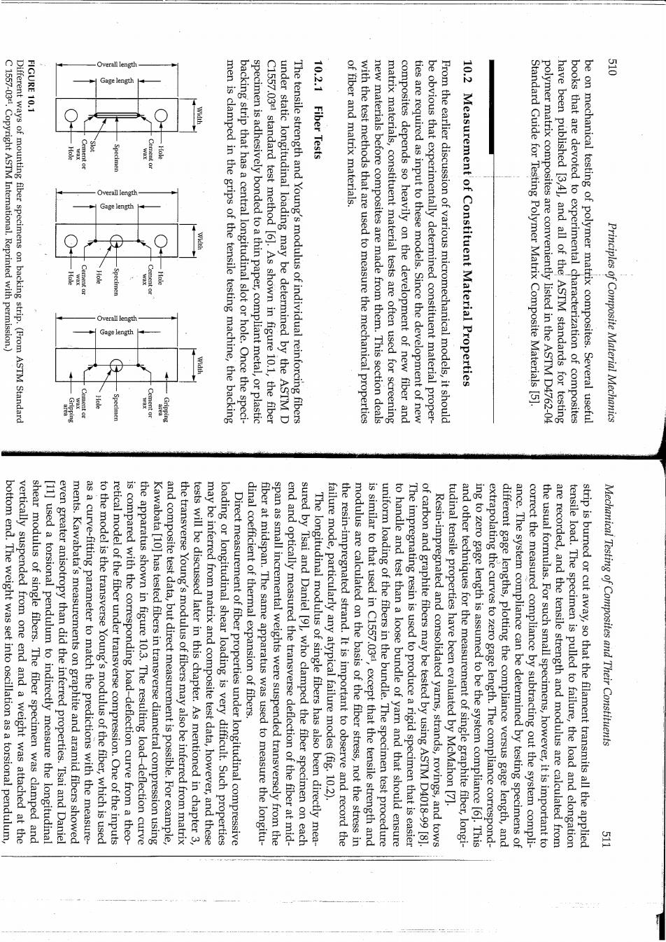
ngt FIGURE 10.1 3 C1557-03.Copyright ASTM International.Reprinted with permission.) Different ways of mounting fiber specimens on backing strip.(From ASTM Standard Overall length men is clamped in the grips of the tensile testing machine,the backing backing strip that has a central longitudinal slot or hole.Once the speci- specimen is adhesively bonded to a thin paper,compliant metal,or plastic C1557.031 standard test method [6].As shown in figure 10.1,the fiber under static longitudinal loading may be determined by the ASTM D The tensile strength and Young's modulus of individual reinforcing fibers 10.2.1 Fiber Tests of fiber and matrix materials. with the test methods that are used to measure the mechanical properties new materials before composites are made from them.This section deals matrix materials,constituent material tests are often used for screening composites depends so heavily on the development of new fiber and ties are required as input to these models.Since the development of new be obvious that experimentally determined constituent material proper- From the earlier discussion of various micromechanical models,it should 10.2 Measurement of Constituent Material Properties Standard Guide for Testing Polymer Matrix Composite Materials [5]. polymer matrix composites are conveniently listed in the ASTM D4762-04 have been published [3,4],and all of the ASTM standards for testing books that are devoted to experimental characterization of composites be on mechanical testing of polymer matrix composites.Several useful Principles of Composite Material Mechanics bottom end.The weight was set into oscillation as a torsional pendulum vertically suspended from one end and a weight was attached at the shear modulus of single fibers.The fiber specimen was clamped and [11]used a torsional pendulum to indirectly measure the longitudinal even greater anisotropy than did the inferred properties.Tsai and Daniel ments.Kawabata's measurements on graphite and aramid fibers showed as a curve-fitting parameter to match the predictions with the measure- to the model is the transverse Young's modulus of the fiber,which is used retical model of the fiber under transverse compression.One of the inputs is compared with the corresponding load-deflection curve from a theo- the apparatus shown in figure 10.3.The resulting load-deflection curve Kawabata [10]has tested fibers in transverse diametral compression using and composite test data,but direct measurement is possible.For example, the transverse Young's modulus of fibers may also be inferred from matrix tests will be discussed later in this chapter.As mentioned in chapter 3, may be inferred from matrix and composite test data,however,and these loading or longitudinal shear loading is very difficult.Such properties Direct measurement of fiber properties under longitudinal compressive dinal coefficient of thermal expansion of fibers. fiber at midspan.The same apparatus was used to measure the longitu- span as small incremental weights were suspended transversely from the end and optically measured the transverse deflection of the fiber at mid- sured by Tsai and Daniel [91,who clamped the fiber specimen on each The longitudinal modulus of single fibers has also been directly mea- failure mode,particularly any atypical failure modes(fig.10.2). the resin-impregnated strand.It is important to observe and record the modulus are calculated on the basis of the fiber stress,not the stress in is similar to that used in C1557.03,except that the tensile strength and uniform loading of the fibers in the bundle.The specimen test procedure to handle and test than a loose bundle of yarn and that should ensure The impregnating resin is used to produce a rigid specimen that is easier of carbon and graphite fibers may be tested by using ASTM D4018-99 [8] Resin-impregnated and consolidated yarns,strands,rovings,and tows tudinal tensile properties have been evaluated by McMahon [7]. and other techniques for the measurement of single graphite fiber,longi- ing to zero gage length is assumed to be the system compliance [61.This extrapolating the curves to zero gage length.The compliance correspond- different gage lengths,plotting the compliance versus gage length,and ance.The system compliance can be determined by testing specimens of correct the measured compliance by subtracting out the system compli- the usual formulas.For such small specimens,however,it is important to are recorded,and the tensile strength and modulus are calculated from tensile load.The specimen is pulled to failure,the load and elongation strip is burned or cut away,so that the filament transmits all the applied Mechanical Testing of Composites and Their Constituents