正在加载图片...

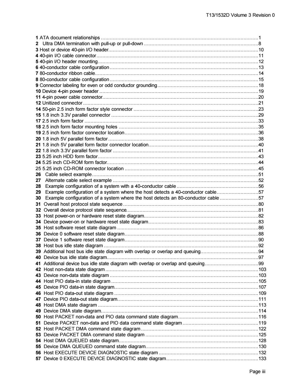
T13/1532D Volume 3 Revision 0 1 ATA document relationships.............. .1 2 Ultra DMA termination with pull-up or pull-down......... 8 3 Host or device 40-pin l/O header....... .10 4 40-pin 1/O cable connector... 5 40-pin l/O header mounting...... 11 .12 640-conductor cable configuration..13 7 80-conductor ribbon cable........ .14 8 80-conductor cable configuration............... .15 9 Connector labeling for even or odd conductor grounding ……….18 10 Device 4-pin power header....... .19 11 4-pin power cable connector................. 20 12 Unitized connector........... .21 14 50-pin 2.5 inch form factor style connector 23 15 1.8 inch 3.3V parallel connector..................... 29 17 2.5 inch form factor ............. .33 18 2.5 inch form factor mounting holes....................... .35 19 2.5 inch form factor connector location.. .36 20 1.8 inch 5V parallel form factor......... .38 21 1.8 inch 5V parallel form factor connector location............... .40 22 1.8 inch 3.3V parallel form factor.. .41 23 5.25 inch HDD form factor....... .43 24 5.25 inch CD-ROM form factor....... .44 25 5.25 inch CD-ROM connector location...... .45 26 Cable select example.......... .51 27 Alternate cable select example..................................... .52 28 Example configuration of a system with a 40-conductor cable............. .56 29 Example configuration of a system where the host detects a 40-conductor cable. .57 30 Example configuration of a system where the host detects an 80-conductor cable........................ .57 31 Overall host protocol state sequence.... .80 32 Overall device protocol state sequence. .81 33 Host power-on or hardware reset state diagram............82 34 Device power-on or hardware reset state diagram...... .83 35 Host software reset state diagram... .86 36 Device o software reset state diagram.. 88 37 Device 1 software reset state diagram...... .90 38 Host bus idle state diagram................... .92 39 Additional host bus idle state diagram with overlap or overlap and queuing..... .94 40 Device bus idle state diagram................. .97 41 Additional device bus idle state diagram with overlap or overlap and queuing. 4444444444444444444444 .99 42 Host non-data state diagram..... 103 43 Device non-data state diagram....... 103 44 Host Plo data-in state diagram..... .105 45 Device PIO data-in state diagram.... .107 46 Host PIO data-out state diagram...... .109 47 Device plo data-out state diagram... .111 48 Host DMA state diagram....................... .113 49 Device DMA state diagram............ .114 50 Host PACKET non-data and PIO data command state diagram... .116 51 Device PACKET non-data and PlO data command state diagram................................. .119 52 Host PACKET DMA command state diagram....... 122 53 Device PACKET DMA command state diagram.... 125 54 Host DMA QUEUED state diagram........... 128 55 Device DMA QUEUED command state diagram................ .130 56 Host EXECUTE DEVICE DIAGNOSTIC state diagram... 132 57 Device 0 EXECUTE DEVICE DIAGNOSTIC state diagram...... .133 Page iiT13/1532D Volume 3 Revision 0 Page iii 1 ATA document relationships ..........................................................................................................1 2 Ultra DMA termination with pull-up or pull-down .............................................................................8 3 Host or device 40-pin I/O header.....................................................................................................10 4 40-pin I/O cable connector.............................................................................................................11 5 40-pin I/O header mounting............................................................................................................12 6 40-conductor cable configuration ....................................................................................................13 7 80-conductor ribbon cable..............................................................................................................14 8 80-conductor cable configuration ....................................................................................................15 9 Connector labeling for even or odd conductor grounding....................................................................18 10 Device 4-pin power header ...........................................................................................................19 11 4-pin power cable connector.........................................................................................................20 12 Unitized connector......................................................................................................................21 14 50-pin 2.5 inch form factor style connector ....................................................................................23 15 1.8 inch 3.3V parallel connector ...................................................................................................29 17 2.5 inch form factor .....................................................................................................................33 18 2.5 inch form factor mounting holes ..............................................................................................35 19 2.5 inch form factor connector location..........................................................................................36 20 1.8 inch 5V parallel form factor.....................................................................................................38 21 1.8 inch 5V parallel form factor connector location..........................................................................40 22 1.8 inch 3.3V parallel form factor ..................................................................................................41 23 5.25 inch HDD form factor............................................................................................................43 24 5.25 inch CD-ROM form factor......................................................................................................44 25 5.25 inch CD-ROM connector location ..........................................................................................45 26 Cable select example................................................................................................................51 27 Alternate cable select example ..................................................................................................52 28 Example configuration of a system with a 40-conductor cable .......................................................56 29 Example configuration of a system where the host detects a 40-conductor cable............................57 30 Example configuration of a system where the host detects an 80-conductor cable ..........................57 31 Overall host protocol state sequence ...........................................................................................80 32 Overall device protocol state sequence.........................................................................................81 33 Host power-on or hardware reset state diagram.............................................................................82 34 Device power-on or hardware reset state diagram..........................................................................83 35 Host software reset state diagram ...............................................................................................86 36 Device 0 software reset state diagram..........................................................................................88 37 Device 1 software reset state diagram..........................................................................................90 38 Host bus idle state diagram ........................................................................................................92 39 Additional host bus idle state diagram with overlap or overlap and queuing.......................................94 40 Device bus idle state diagram......................................................................................................97 41 Additional device bus idle state diagram with overlap or overlap and queuing....................................99 42 Host non-data state diagram .......................................................................................................103 43 Device non-data state diagram ....................................................................................................103 44 Host PIO data-in state diagram ...................................................................................................105 45 Device PIO data-in state diagram.................................................................................................107 46 Host PIO data-out state diagram .................................................................................................109 47 Device PIO data-out state diagram...............................................................................................111 48 Host DMA state diagram ............................................................................................................113 49 Device DMA state diagram..........................................................................................................114 50 Host PACKET non-data and PIO data command state diagram......................................................116 51 Device PACKET non-data and PIO data command state diagram ...................................................119 52 Host PACKET DMA command state diagram ...............................................................................122 53 Device PACKET DMA command state diagram ............................................................................125 54 Host DMA QUEUED state diagram..............................................................................................128 55 Device DMA QUEUED command state diagram............................................................................130 56 Host EXECUTE DEVICE DIAGNOSTIC state diagram ...................................................................132 57 Device 0 EXECUTE DEVICE DIAGNOSTIC state diagram..............................................................133