正在加载图片...

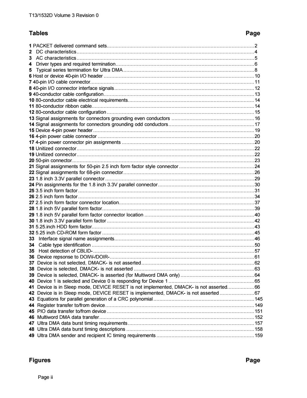
T13/1532D Volume 3 Revision 0 Tables Page 1 PACKET delivered command sets............... 2 2 DC characteristics..4 3 AC characteristics.... 4 Driver types and required termination...6 5 Typical series termination for Ultra DMA.....8 6 Host or device 40-pin I/O header.... 10 7 40-pin l/O cable connector................... 11 8 40-pin 1/O connector interface signals................. …12 9 40-conductor cable configuration......... 13 10 80-conductor cable electrical requirements......................... 4444444444444444440444444444444044 14 11 80-conductor ribbon cable.......... .14 12 80-conductor cable configuration...... .15 13 Signal assignments for connectors grounding even conductors 16 14 Signal assignments for connectors grounding odd conductors. 1 15 Device 4-pin power header. 19 164-pin power cable connector. 20 17 4-pin power connector pin assignments........ 20 18 Unitized connector... 22 19 Unitized connector... 22 20 50-pin connector....... 23 21 Signal assignments for 50-pin 2.5 inch form factor style connector 444444 24 22 Signal assignments for 68-pin connector..................... 26 23 1.8 inch 3.3V parallel connector............ 29 24 Pin assignments for the 1.8 inch 3.3V parallel connector............ 444444 30 25 3.5 inch form factor.............. 31 26 2.5 inch form factor.......... 34 272.5 inch form factor connector location.37 28 1.8 inch 5V parallel form factor.............. 39 29 1.8 inch 5V parallel form factor connector location 40 30 1.8 inch 3.3vparallel form factor. 42 31 5.25.inch HDD form factor...................... 43 32 5.25 inch CD-ROM form factor........... 44444 45 33 Interface signal name assignments............. 46 34 Cable type identification....... 50 35 Host detection of CBLID-... 44404444444404444044440444444440 57 36 Device repsonse to DOIW-/DOIR-....... 61 37 Device is not selected,DMACK-is not asserted................... 62 38 Device is selected,DMACK-is not asserted....63 39 Device is selected,DMACK-is asserted (for Multiword DMA only).... 64 40 Device 1 is selected and Device 0 is responding for Device 1........... 65 41 Device is in Sleep mode,DEVICE RESET is not implemented,DMACK-is not asserted.................. 6 42 Device is in Sleep mode,DEVICE RESET is implemented,DMACK-is not asserted.......................67 43 Equations for parallel generation of a CRC polynomial..... 145 44 Register transfer to/from device.149 45 PlO data transfer to/from device........................... 151 46 Multiword DMA data transfer.. 152 47 Ultra DMA data burst timing requirements.......... 157 48 Ultra DMA data burst timing descriptions. 158 49 Ultra DMA sender and recipient Ic timing requirements.......................................159 Figures Page Page iiT13/1532D Volume 3 Revision 0 Page ii Tables Page 1 PACKET delivered command sets..................................................................................................2 2 DC characteristics......................................................................................................................4 3 AC characteristics......................................................................................................................5 4 Driver types and required termination............................................................................................6 5 Typical series termination for Ultra DMA.......................................................................................8 6 Host or device 40-pin I/O header ....................................................................................................10 7 40-pin I/O cable connector.............................................................................................................11 8 40-pin I/O connector interface signals.............................................................................................12 9 40-conductor cable configuration....................................................................................................13 10 80-conductor cable electrical requirements....................................................................................14 11 80-conductor ribbon cable............................................................................................................14 12 80-conductor cable configuration ..................................................................................................15 13 Signal assignments for connectors grounding even conductors .......................................................16 14 Signal assignments for connectors grounding odd conductors.........................................................17 15 Device 4-pin power header...........................................................................................................19 16 4-pin power cable connector ........................................................................................................20 17 4-pin power connector pin assignments ........................................................................................20 18 Unitized connector......................................................................................................................22 19 Unitized connector......................................................................................................................22 20 50-pin connector.........................................................................................................................23 21 Signal assignments for 50-pin 2.5 inch form factor style connector..................................................24 22 Signal assignments for 68-pin connector.......................................................................................26 23 1.8 inch 3.3V parallel connector...................................................................................................29 24 Pin assignments for the 1.8 inch 3.3V parallel connector................................................................30 25 3.5 inch form factor.....................................................................................................................31 26 2.5 inch form factor.....................................................................................................................34 27 2.5 inch form factor connector location..........................................................................................37 28 1.8 inch 5V parallel form factor.....................................................................................................39 29 1.8 inch 5V parallel form factor connector location .........................................................................40 30 1.8 inch 3.3V parallel form factor..................................................................................................42 31 5.25.inch HDD form factor............................................................................................................43 32 5.25 inch CD-ROM form factor .....................................................................................................45 33 Interface signal name assignments.............................................................................................46 34 Cable type identification ............................................................................................................50 35 Host detection of CBLID-...........................................................................................................57 36 Device repsonse to DOIW-/DOIR-................................................................................................61 37 Device is not selected, DMACK- is not asserted...........................................................................62 38 Device is selected, DMACK- is not asserted ................................................................................63 39 Device is selected, DMACK- is asserted (for Multiword DMA only).................................................64 40 Device 1 is selected and Device 0 is responding for Device 1 .........................................................65 41 Device is in Sleep mode, DEVICE RESET is not implemented, DMACK- is not asserted..................66 42 Device is in Sleep mode, DEVICE RESET is implemented, DMACK- is not asserted .......................67 43 Equations for parallel generation of a CRC polynomial ...................................................................145 44 Register transfer to/from device...................................................................................................149 45 PIO data transfer to/from device ..................................................................................................151 46 Multiword DMA data transfer.......................................................................................................152 47 Ultra DMA data burst timing requirements....................................................................................157 48 Ultra DMA data burst timing descriptions .....................................................................................158 49 Ultra DMA sender and recipient IC timing requirements .................................................................159 Figures Page