正在加载图片...
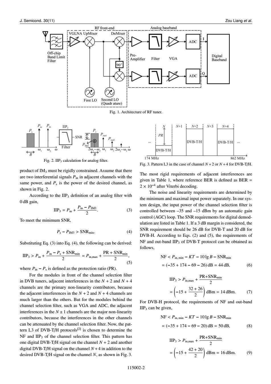
J.Semicond.30(11) Zou Liang et al. RF front-end Analog baseband VGLNA UpMixer DnMixer ADC Off-chip Band Limit Pre- Filter Digital Filter Amplifier VGA Baseband 90 ADC First LO Second LO (Quadr ature) Fig.1.Architecture of RF tuner. HP. N+1 N+21 N+3 i N+4 PR DVB-T/H DVB-T/H Filter DVB-T/H 174 MHz Fig.2.IIP3 calculation for analog filter. 862MH Fig.3.Pattern L3 in the case of channel N+2 or N+4 for DVB-T/H. product of IM3 must be rigidly constrained.Assume that there The most rigid requirements of adjacent interferences are are two interferential signals Pin in adjacent channels with the same power,and Ps is the power of the desired channel,as given in Table 1,where reference BER is defined as BER shown in Fig.2. 2x 10⁻⁴ after Viterbi decoding. The noise and linearity requirements are determined by According to the IIP definition of an analog filter with the minimum and maximal input power separately.In our sys- 0dB gain, IIPs=Pn+t Pin-PIMs tem design,the input power of the channel selection filter is 2 (3) controlled between -35 and-15 dBm by an automatic gain control(AGC)loop.The SNR requirements for digital demod- To meet the minimum SNR. ulation are listed in Table 1.If a 3 dB margin is considered,the Ps -PIM3 SNRmin. (4) SNR requirement should be 26 dB for DVB-T and 20 dB for DVB-H.According to Egs.(2)and(5),the requirements of Substituting Eq.(3)into Eq.(4),the following can be derived: NF and out-band IIP3 of DVB-T protocol can be obtained as follows, IIP3 >Pm-P.+SNRan Pnma PR+SNRmin 2 NF<Pin.min -KT-101g B-SNRmin (5) =(-35+174-69-26)dB=44dB. (6) where Pin-Ps is defined as the protection ratio(PR). For the modules in front of the channel selection filter in DVB tuners,adjacent interferences in the N +2 and N+4 IIP3>PPR+SNRmin 2 channels are the primary non-linearity contributors,because the adjacent interferences in the N+2 and N+4 channels are -15+22 dBm 14dBm. (7) much larger than the others.But for the modules behind the For DVB-H protocol,the requirements of NF and out-band channel selection filter,such as VGA and ADC.the adjacent IIP can be given. interferences in the N+1 channels are the major non-linearity contributors,because the interferences in the other channels NF<Pin.min -KT-101g B-SNRmin can be attenuated by the channel selection filter.Now,the pat- =(-35+174-69-20)dB=50dB. (8) tern L3 of DVB-T/H protocols21 is chosen to determine the NF and IIP3 of the channel selection filter.This pattern has PR+SNRmin one digital DVB-T/H signal on the channel N+2 and another IIP3 Pin.max 2 digital DVB-T/H signal on the channel N+4 in addition to the desired DVB-T/H signal on the channel N,as shown in Fig.3. 15+42+20 2 dBm 16dBm (9) 115002-2J. Semicond. 30(11) Zou Liang et al. Fig. 1. Architecture of RF tuner. Fig. 2. IIP3 calculation for analog filter. product of IM3 must be rigidly constrained. Assume that there are two interferential signals Pin in adjacent channels with the same power, and Ps is the power of the desired channel, as shown in Fig. 2. According to the IIP3 definition of an analog filter with 0 dB gain, IIP3 = Pin + Pin − PIM3 2 . (3) To meet the minimum SNR, Ps − PIM3 > SNRmin. (4) Substituting Eq. (3) into Eq. (4), the following can be derived: IIP3 > Pin + Pin − Ps + SNRmin 2 = Pin,max + PR + SNRmin 2 , (5) where Pin − Ps is defined as the protection ratio (PR). For the modules in front of the channel selection filter in DVB tuners, adjacent interferences in the N + 2 and N + 4 channels are the primary non-linearity contributors, because the adjacent interferences in the N + 2 and N + 4 channels are much larger than the others. But for the modules behind the channel selection filter, such as VGA and ADC, the adjacent interferences in the N ± 1 channels are the major non-linearity contributors, because the interferences in the other channels can be attenuated by the channel selection filter. Now, the pattern L3 of DVB-T/H protocols[2] is chosen to determine the NF and IIP3 of the channel selection filter. This pattern has one digital DVB-T/H signal on the channel N + 2 and another digital DVB-T/H signal on the channel N +4 in addition to the desired DVB-T/H signal on the channel N, as shown in Fig. 3. Fig. 3. Pattern L3 in the case of channel N +2 or N +4 for DVB-T/H. The most rigid requirements of adjacent interferences are given in Table 1, where reference BER is defined as BER = 2 × 10⁻⁴ after Viterbi decoding. The noise and linearity requirements are determined by the minimum and maximal input power separately. In our system design, the input power of the channel selection filter is controlled between –35 and –15 dBm by an automatic gain control (AGC) loop. The SNR requirements for digital demodulation are listed in Table 1. If a 3 dB margin is considered, the SNR requirement should be 26 dB for DVB-T and 20 dB for DVB-H. According to Eqs. (2) and (5), the requirements of NF and out-band IIP3 of DVB-T protocol can be obtained as follows, NF < Pin, min − KT − 10 lg B − SNRmin = (−35 + 174 − 69 − 26) dB = 44 dB, (6) IIP3 > Pin,max + PR+SNRmin 2 = ( −15 + 32 + 26 2 ) dBm = 14 dBm. (7) For DVB-H protocol, the requirements of NF and out-band IIP3 can be given, NF < Pin, min − KT − 10 lg B − SNRmin = (−35 + 174 − 69 − 20) dB = 50 dB, (8) IIP3 > Pin,max + PR+SNRmin 2 = ( −15 + 42 + 20 2 ) dBm = 16 dBm. (9) 115002-2