正在加载图片...
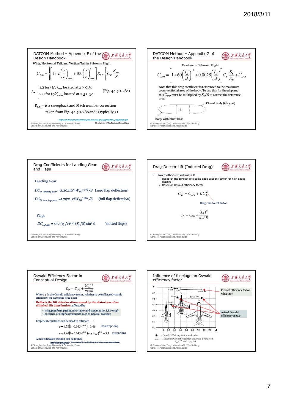
2018/3/11 DATCOM Method-AppendixFof the国上活支美大聋 DATCOM Method -Appendix G of Design Handbook the Design Handbook 国上清大学 Wing.Horizontal Tail,and Vertical Tail in Subsonic Flight Fuselage in Subsonic Flight 1.2 for(t/e)located atx0.3c Note that this drag coefficient is referenced to the maximum (Fig4.1.5.1-28a) cross-sectional area of the body.To use this for the airplane 2.0 for (t/c)located at x<o.3c this Cpo must be multiplied by S/Sto correct the reference area Rs.=is a sweepback and Mach number correction Closed body(Cp=o) taken from Fig.4.1.5.1-28b and is typically >1 Body with blunt base oandn ong Drag Coefficients for Landing Gear and Flaps 圆上清道大坐 Drag-Due-to-Lift (Induced Drag) 园上活道大整 Two methods to estimate K Landing Gear -Based on the concept of leading edge suction(better for high-speed designs) -Based on Oswald efficiency factor DCp.ding=3-30x103Wro/(zero flap deflection) Cp=Cpo+KCi DCp.lndin r=179x103Wo/S (full flap deflection) Drag-due-to-lift factor Flaps Cp=CDo+ C)2 eAR DCpnaps=0.9(c/c)(S/S)sind (slotted flaps) nwentin ong oerandenn ong Oswald Efficiency Factor in Influence of fuselage on Oswald Conceptual Design 国上清大学 efficiency factor 园上海发大坐 Cp=Cpo+ (C)2 Oswald efficiency factor wing onlv 0.8 Reflects the lift deterioration eaused by the distortion of an elliptical lift distribution,affected by wing planform parameters (taper and aspect ratio,LE sweep) 06 .presence of other components such as nacelle,fuselage Actual Oswald 0.5 efficiency factor Empirical equations can be used to estimate e 0.4- e=1.78l-0.0454-0.46 Unsweep wing 1.3 0203.04030607.08090A e=4.611-0.045Ycos AL)15-3.1 sweep wing Oswald efficieney factor real value A more detailed method can be found: 。一,Maximum Oswald eficiency ctorfowing with A=27d00 slty-Dr.W(enbin Song 72018/3/11 7 © Shanghai Jiao Tong University – Dr. Wenbin Song School of Aeronautics and Astronautics DATCOM Method – Appendix F of the Design Handbook Wing, Horizontal Tail, and Vertical Tail in Subsonic Flight 4 ,0 . . max max 1 100 wet D L S F t t S C L R C c c S L= 1.2 for (t/c)max located at x > 0.3c 2.0 for (t/c)max located at x < 0.3c RL.S. = is a sweepback and Mach number correction taken from Fig. 4.1.5.1-28b and is typically >1 (Fig. 4.1.5.1-28a) http://ntrs.nasa.gov/archive/nasa/casi.ntrs.nasa.gov/19930090976_1993090976.pdf New link for NACA Technical Report 824. © Shanghai Jiao Tong University – Dr. Wenbin Song School of Aeronautics and Astronautics DATCOM Method – Appendix G of the Design Handbook Fuselage in Subsonic Flight 3 ,0 , 1 60 0.0025 B B S D F D b B l l S C C C d d S Note that this drag coefficient is referenced to the maximum cross-sectional area of the body. To use this for the airplane this CD,0 must be multiplied by SB /S to correct the reference area Body with blunt base Closed body (CD,b=0) d © Shanghai Jiao Tong University – Dr. Wenbin Song School of Aeronautics and Astronautics Drag Coefficients for Landing Gear and Flaps DCD, landing gear =3.30x10⁻³WTO 0.785 /S (zero flap deflection) DCD, landing gear =1.79x10⁻³WTO 0.785 /S (full flap deflection) DCD,flaps = 0.9 (cf /c)1.38 (Sf /S) sin2 d (slotted flaps) Landing Gear Flaps © Shanghai Jiao Tong University – Dr. Wenbin Song School of Aeronautics and Astronautics Drag-Due-to-Lift (Induced Drag) • Two methods to estimate K – Based on the concept of leading edge suction (better for high-speed designs) – Based on Oswald efficiency factor 2 CD CD0 KCL Drag-due-to-lift factor © Shanghai Jiao Tong University – Dr. Wenbin Song School of Aeronautics and Astronautics Oswald Efficiency Factor in Conceptual Design Samoylovitch, O. and Strelets D., “Determination of the Oswald efficiency factor at the aeroplane design preliminary stage”, Aircraft Design 3(2000) Where is the Oswald efficiency factor, relating to overall aerodynamic efficiency, for parabolic drag polar Reflects the lift deterioration caused by the distortion of an elliptical lift distribution, affected by • wing planform parameters (taper and aspect ratio, LE sweep) • presence of other components such as nacelle, fuselage e Empirical equations can be used to estimate e 1.781 0.045 0.46 0.68 e A 4.611 0.045 cos 3.1 0.68 0.15 e A LE Unsweep wing sweep wing A more detailed method can be found: © Shanghai Jiao Tong University – Dr. Wenbin Song School of Aeronautics and Astronautics Influence of fuselage on Oswald efficiency factor Oswald efficiency factor wing only Actual Oswald efficiency factor