正在加载图片...

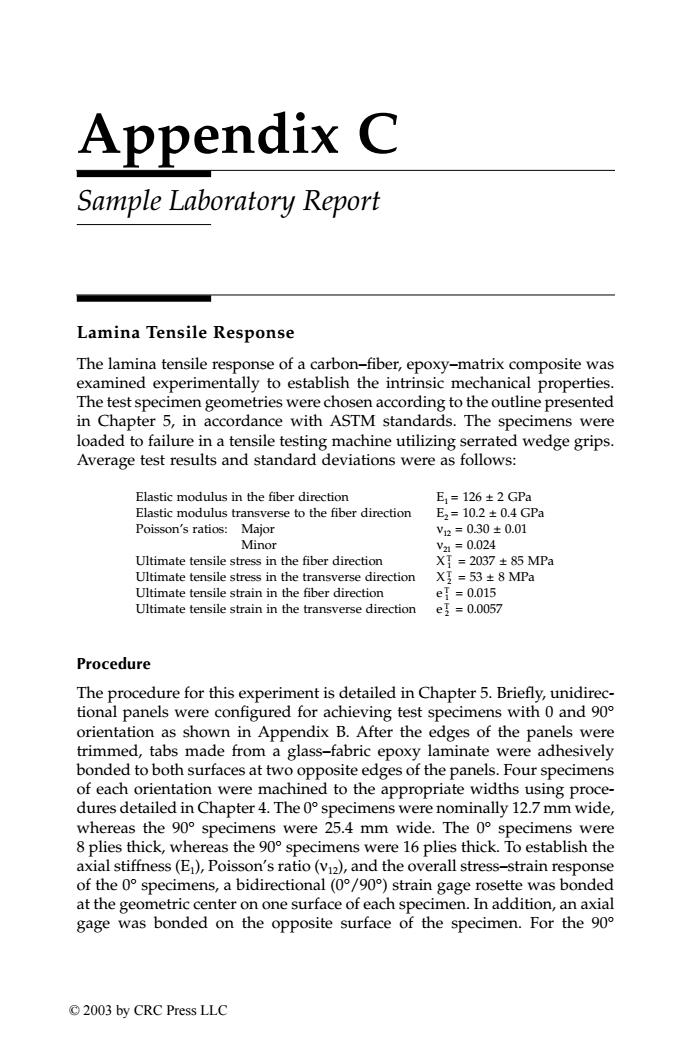
Appendix C Sample Laboratory Report Lamina Tensile Response The lamina tensile response of a carbon-fiber,epoxy-matrix composite was examined experimentally to establish the intrinsic mechanical properties. The test specimen geometries were chosen according to the outline presented in Chapter 5,in accordance with ASTM standards.The specimens were loaded to failure in a tensile testing machine utilizing serrated wedge grips. Average test results and standard deviations were as follows: Elastic modulus in the fiber direction E1=126±2GPa Elastic modulus transverse to the fiber direction E2=10.2±0.4GPa Poisson's ratios:Major v2=0.30±0.01 Minor V2a-0.024 Ultimate tensile stress in the fiber direction XT=2037±85MPa Ultimate tensile stress in the transverse direction Xg-53±8MPa Ultimate tensile strain in the fiber direction e=0.015 Ultimate tensile strain in the transverse direction e1-0.0057 Procedure The procedure for this experiment is detailed in Chapter 5.Briefly,unidirec- tional panels were configured for achieving test specimens with 0 and 900 orientation as shown in Appendix B.After the edges of the panels were trimmed,tabs made from a glass-fabric epoxy laminate were adhesively bonded to both surfaces at two opposite edges of the panels.Four specimens of each orientation were machined to the appropriate widths using proce- dures detailed in Chapter 4.The 0 specimens were nominally 12.7 mm wide, whereas the 90 specimens were 25.4 mm wide.The 0 specimens were 8 plies thick,whereas the 90 specimens were 16 plies thick.To establish the axial stiffness(E),Poisson's ratio (v2),and the overall stress-strain response of the 0 specimens,a bidirectional(0/90)strain gage rosette was bonded at the geometric center on one surface of each specimen.In addition,an axial gage was bonded on the opposite surface of the specimen.For the 90 ©2003 by CRC Press LLCAppendix C Sample Laboratory Report Lamina Tensile Response The lamina tensile response of a carbon–fiber, epoxy–matrix composite was examined experimentally to establish the intrinsic mechanical properties. The test specimen geometries were chosen according to the outline presented in Chapter 5, in accordance with ASTM standards. The specimens were loaded to failure in a tensile testing machine utilizing serrated wedge grips. Average test results and standard deviations were as follows: Procedure The procedure for this experiment is detailed in Chapter 5. Briefly, unidirectional panels were configured for achieving test specimens with 0 and 90° orientation as shown in Appendix B. After the edges of the panels were trimmed, tabs made from a glass–fabric epoxy laminate were adhesively bonded to both surfaces at two opposite edges of the panels. Four specimens of each orientation were machined to the appropriate widths using procedures detailed in Chapter 4. The 0° specimens were nominally 12.7 mm wide, whereas the 90° specimens were 25.4 mm wide. The 0° specimens were 8 plies thick, whereas the 90° specimens were 16 plies thick. To establish the axial stiffness (E1), Poisson’s ratio (ν12), and the overall stress–strain response of the 0° specimens, a bidirectional (0°/90°) strain gage rosette was bonded at the geometric center on one surface of each specimen. In addition, an axial gage was bonded on the opposite surface of the specimen. For the 90° Elastic modulus in the fiber direction E1 = 126 ± 2 GPa Elastic modulus transverse to the fiber direction E2 = 10.2 ± 0.4 GPa Poisson’s ratios: Major ν12 = 0.30 ± 0.01 Minor ν21 = 0.024 Ultimate tensile stress in the fiber direction X 1 T = 2037 ± 85 MPa Ultimate tensile stress in the transverse direction X 2 T = 53 ± 8 MPa Ultimate tensile strain in the fiber direction e 1 T = 0.015 Ultimate tensile strain in the transverse direction e 2 T = 0.0057 TX001_AppC_Frame Page 227 Saturday, September 21, 2002 5:14 AM © 2003 by CRC Press LLC