正在加载图片...
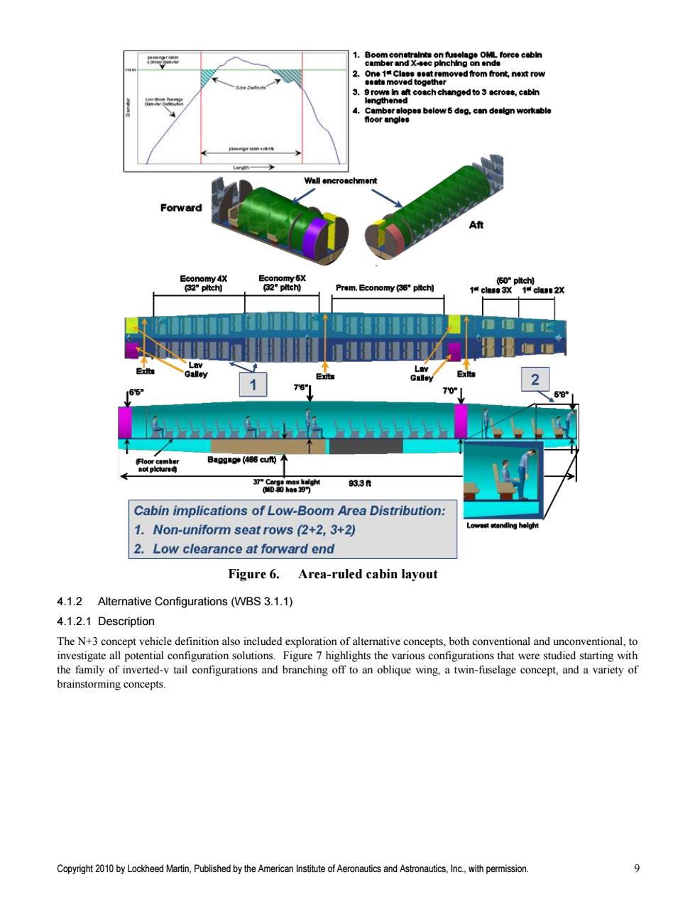
1.Boom constraints on fuselage OML force cabin camber and X-sec plnching on ends 2. One 1 Class seat removed from front,next row 参ats moved to9ther 3.9rows in aft coach changed to 3 across,cabin lengthened 4.Camber slopes below 5 deg,can design workable noor angle垂 Wall encroachment Forward Aft Economy 4X Economy5X (50"pltch) (32"pltch] (32"pitch) Prem.Economy (36"pltch) Galley 165* 70° 58” 月oor camher Ba99(466c not picture 933量 Cabin implications of Low-Boom Area Distribution: 1.Non-uniform seat rows (2+2,3+2) Lowest standing helght 2.Low clearance at forward end Figure 6.Area-ruled cabin layout 4.1.2 Alternative Configurations (WBS 3.1.1) 4.1.2.1 Description The N+3 concept vehicle definition also included exploration of alternative concepts,both conventional and unconventional,to investigate all potential configuration solutions.Figure 7 highlights the various configurations that were studied starting with the family of inverted-v tail configurations and branching off to an oblique wing,a twin-fuselage concept,and a variety of brainstorming concepts. Copyright 2010 by Lockheed Martin,Published by the American Institute of Aeronautics and Astronautics,Inc.,with permission. 9Copyright 2010 by Lockheed Martin, Published by the American Institute of Aeronautics and Astronautics, Inc., with permission. 9 Figure 6. Area-ruled cabin layout 4.1.2 Alternative Configurations (WBS 3.1.1) 4.1.2.1 Description The N+3 concept vehicle definition also included exploration of alternative concepts, both conventional and unconventional, to investigate all potential configuration solutions. Figure 7 highlights the various configurations that were studied starting with the family of inverted-v tail configurations and branching off to an oblique wing, a twin-fuselage concept, and a variety of brainstorming concepts