正在加载图片...
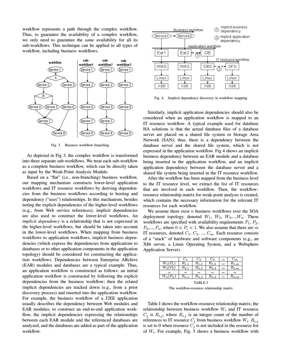
workflow represents a path through the complex workflow. Implicit business Business workflow ① dependency Thus,to guarantee the availability of a complex workflow, Service1 Service2 we only need to guarantee the same availability for all its Implicit application dependency sub-workflows.This technique can be applied to all types of Application workflow workflow,including business workflows. Ear1 Ear2- Ol DB sub- sub- sub- IT resource workflow workflow workflow1 workflow2 workflow3 WAS WAS DB2 SFS Service 1 (Service 1 (Service 1 Service 1 Linux Linux nux inux Service 3 (Service 2 (Service 2 X86 X86 X86 Fig.4. Implicit dependency discovery in workflow mapping Service 4 Service 5 Service 6 (Service 4 Service 5 Service 6 Similarly,implicit application dependencies should also be considered when an application workflow is mapped to an (Service 7 IT resource workflow.A typical example used for database HA solutions is that the actual database files of a database Service 8 (Service 8 (Service 8 (Service 8 server are placed on a shared file system or Storage Area Network (SAN);thus,there is a dependency between the Fig.3.Business workflow branching database server and the shared file system,which is not expressed in the application workflow.Fig 4 shows an implicit As depicted in Fig 3,the complex workflow is transformed business dependency between an EAR module and a database into three separate sub-workflows.We treat each sub-workflow being inserted in the application workflow,and an implicit as a complete business workflow,which can be directly taken application dependency between the database server and a as input by the Weak-Point Analysis Module. shared file system being inserted in the IT resource workflow. Based on a "flat"(i.e.,non-branching)business workflow, After the workflow has been mapped from the business level our mapping mechanism constructs lower-level application to the IT resource level,we extract the list of IT resources workflows and IT resource workflows by deriving dependen- that are involved in each workflow.Then,the workflow- cies from the business workflows according to hosting and resource relationship matrix for weak-point analysis is created, dependency ("uses")relationships.In this mechanism,besides which contains the necessary information for the relevant IT noting the explicit dependencies of the higher-level workflows resources for each workflow. (e.g..from Web service references),implicit dependencies We assume there exist n business workflows over the SOA are also used to construct the lower-level workflows.An deployment topology,denoted Wi,W2.W3.....Wn.These implicit dependency is a relationship that is not expressed in workflows are specified with availability requirements P.P2. the higher-level workflows,but should be taken into account P3,...,P,where 0<P<1.We also assume that there are m in the lower-level workflows.When mapping from business IT resources,denoted C1,C2....Cm.Each resource consists workflows to application workflows,implicit business depen- of a "stack"of hardware and software components (e.g.,an dencies(which express the dependencies from applications to X86 server,a Linux Operating System,and a Websphere databases or to other application components in the application Application Server). topology)should be considered for constructing the applica- tion workflows.Dependencies between Enterprise ARchive C1 C02 C3 年 Cm (EAR)modules and databases are a typical example.Thus. WP R1.1 R1.2R1.3 Ri.m an application workflow is constructed as follows:an initial W2P2■ 2.1 R2.2■2.3 R2.m application workflow is constructed by following the explicit Wn(Pn)Rn.1 Rn.2 Rn.3 Rn.m dependencies from the business workflow:then the related TABLE I implicit dependencies are tracked down (e.g.,from a prior The workflow-resource relationship matrix discovery process)and inserted into the application workflow. For example,the business workflow of a J2EE application usually describes the dependency between Web modules and Table I shows the workflow-resource relationship matrix;the EAR modules;to construct an end-to-end application work- relationship between business workflow Wi and IT resource flow,the implicit dependencies expressing the relationships Ci is Ri.j,where Ri;is an integer count of the number of between each EAR module and the referenced databases are references to IT resource C;from business workflow Wi.Ri.j analyzed,and the databases are added as part of the application is set to 0 when resource C;is not included in the resource list workflow. of Wi.For example,Fig.5 shows a business workflow withworkflow represents a path through the complex workflow. Thus, to guarantee the availability of a complex workflow, we only need to guarantee the same availability for all its sub-workflows. This technique can be applied to all types of workflow, including business workflows. Fig. 3. Business workflow branching As depicted in Fig 3, the complex workflow is transformed into three separate sub-workflows. We treat each sub-workflow as a complete business workflow, which can be directly taken as input by the Weak-Point Analysis Module. Based on a “flat” (i.e., non-branching) business workflow, our mapping mechanism constructs lower-level application workflows and IT resource workflows by deriving dependencies from the business workflows according to hosting and dependency (“uses”) relationships. In this mechanism, besides noting the explicit dependencies of the higher-level workflows (e.g., from Web service references), implicit dependencies are also used to construct the lower-level workflows. An implicit dependency is a relationship that is not expressed in the higher-level workflows, but should be taken into account in the lower-level workflows. When mapping from business workflows to application workflows, implicit business dependencies (which express the dependencies from applications to databases or to other application components in the application topology) should be considered for constructing the application workflows. Dependencies between Enterprise ARchive (EAR) modules and databases are a typical example. Thus, an application workflow is constructed as follows: an initial application workflow is constructed by following the explicit dependencies from the business workflow; then the related implicit dependencies are tracked down (e.g., from a prior discovery process) and inserted into the application workflow. For example, the business workflow of a J2EE application usually describes the dependency between Web modules and EAR modules; to construct an end-to-end application work- flow, the implicit dependencies expressing the relationships between each EAR module and the referenced databases are analyzed, and the databases are added as part of the application workflow. Fig. 4. Implicit dependency discovery in workflow mapping Similarly, implicit application dependencies should also be considered when an application workflow is mapped to an IT resource workflow. A typical example used for database HA solutions is that the actual database files of a database server are placed on a shared file system or Storage Area Network (SAN); thus, there is a dependency between the database server and the shared file system, which is not expressed in the application workflow. Fig 4 shows an implicit business dependency between an EAR module and a database being inserted in the application workflow, and an implicit application dependency between the database server and a shared file system being inserted in the IT resource workflow. After the workflow has been mapped from the business level to the IT resource level, we extract the list of IT resources that are involved in each workflow. Then, the workflowresource relationship matrix for weak-point analysis is created, which contains the necessary information for the relevant IT resources for each workflow. We assume there exist n business workflows over the SOA deployment topology, denoted W1, W2, W3,...,Wn. These workflows are specified with availability requirements P1, P2, P3,..., Pn, where 0 < Pi < 1. We also assume that there are m IT resources, denoted C1, C2, ..., Cm. Each resource consists of a “stack” of hardware and software components (e.g., an X86 server, a Linux Operating System, and a Websphere Application Server). C1 C2 C3 ... Cm W1(P1) R1,1 R1,2 R1,3 ... R1,m W2(P2) R2,1 R2,2 R2,3 ... R2,m ... ... ... ... ... ... Wn(Pn) Rn,1 Rn,2 Rn,3 ... Rn,m TABLE I The workflow-resource relationship matrix Table I shows the workflow-resource relationship matrix; the relationship between business workflow Wi and IT resource Cj is Ri,j , where Ri,j is an integer count of the number of references to IT resource Cj from business workflow Wi . Ri,j is set to 0 when resource Cj is not included in the resource list of Wi . For example, Fig. 5 shows a business workflow with