正在加载图片...
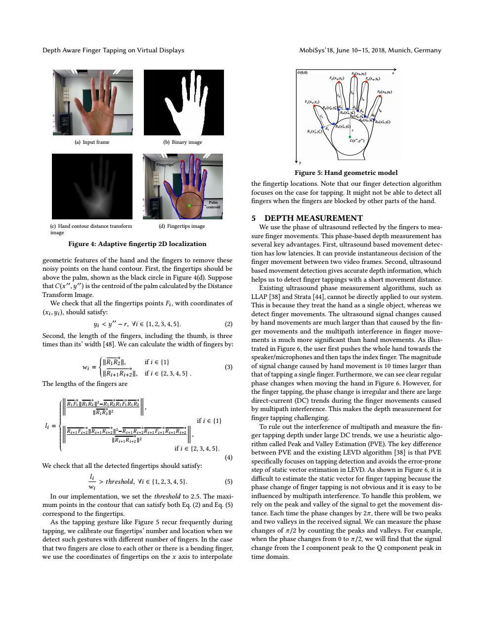
Depth Aware Finger Tapping on Virtual Displays MobiSys'18,June 10-15,2018,Munich,Germany 00, .v (a)Input frame (b)Binary Figure 5:Hand geometric model the fingertip locations.Note that our finger detection algorithm focuses on the case for tapping.It might not be able to detect all fingers when the fingers are blocked by other parts of the hand. 5 DEPTH MEASUREMENT (c)Hand contour distance transform (d)Fingertips image We use the phase of ultrasound reflected by the fingers to mea- image sure finger movements.This phase-based depth measurement has Figure 4:Adaptive fingertip 2D localization several key advantages.First,ultrasound based movement detec- tion has low latencies.It can provide instantaneous decision of the geometric features of the hand and the fingers to remove these finger movement between two video frames.Second,ultrasound noisy points on the hand contour.First,the fingertips should be based movement detection gives accurate depth information,which above the palm,shown as the black circle in Figure 4(d).Suppose helps us to detect finger tappings with a short movement distance. that C(x"y")is the centroid of the palm calculated by the Distance Existing ultrasound phase measurement algorithms,such as Transform Image. LLAP [38]and Strata [44].cannot be directly applied to our system. We check that all the fingertips points Fi,with coordinates of This is because they treat the hand as a single object,whereas we (xi,yi),should satisfy: detect finger movements.The ultrasound signal changes caused 班<y”-r,ie{1,2,3,4,5. (2) by hand movements are much larger than that caused by the fin- Second,the length of the fingers,including the thumb,is three ger movements and the multipath interference in finger move- times than its'width [48].We can calculate the width of fingers by: ments is much more significant than hand movements.As illus- trated in Figure 6,the user first pushes the whole hand towards the speaker/microphones and then taps the index finger.The magnitude IR:R2ll. ifie(1) (3) of signal change caused by hand movement is 10 times larger than RiRi+2ll.if i E12.3.4.51. that of tapping a single finger.Furthermore,we can see clear regular The lengths of the fingers are phase changes when moving the hand in Figure 6.However,for the finger tapping.the phase change is irregular and there are large RFRR-R1RRFRR direct-current(DC)trends during the finger movements caused R1R22 by multipath interference.This makes the depth measurement for ifie(1) finger tapping challenging. R1E+R+1R+2-R1R1+2R11EiR1+1R+2 To rule out the interference of multipath and measure the fin- R+1R1+2 ger tapping depth under large DC trends,we use a heuristic algo- ifi∈{2,3,4,5. rithm called Peak and Valley Estimation(PVE).The key difference between PVE and the existing LEVD algorithm [38]is that PVE (4) We check that all the detected fingertips should satisfy: specifically focuses on tapping detection and avoids the error-prone step of static vector estimation in LEVD.As shown in Figure 6,it is threshold,Yi E(1,2,3,4,51 (5) difficult to estimate the static vector for finger tapping because the phase change of finger tapping is not obvious and it is easy to be In our implementation,we set the threshold to 2.5.The maxi- influenced by multipath interference.To handle this problem,we mum points in the contour that can satisfy both Eq.(2)and Eq.(5) rely on the peak and valley of the signal to get the movement dis- correspond to the fingertips. tance.Each time the phase changes by 2n,there will be two peaks As the tapping gesture like Figure 5 recur frequently during and two valleys in the received signal.We can measure the phase tapping,we calibrate our fingertips'number and location when we changes of /2 by counting the peaks and valleys.For example. detect such gestures with different number of fingers.In the case when the phase changes from 0 to /2,we will find that the signal that two fingers are close to each other or there is a bending finger change from the I component peak to the O component peak in we use the coordinates of fingertips on the x axis to interpolate time domain.Depth Aware Finger Tapping on Virtual Displays MobiSys’18, June 10–15, 2018, Munich, Germany (a) Input frame (b) Binary image (c) Hand contour distance transform image (d) Fingertips image Figure 4: Adaptive fingertip 2D localization geometric features of the hand and the fingers to remove these noisy points on the hand contour. First, the fingertips should be above the palm, shown as the black circle in Figure 4(d). Suppose thatC(x ′′ ,y ′′) is the centroid of the palm calculated by the Distance Transform Image. We check that all the fingertips points Fi , with coordinates of (xi ,yi ), should satisfy: yi < y ′′ − r, ∀i ∈ {1, 2, 3, 4, 5}. (2) Second, the length of the fingers, including the thumb, is three times than its’ width [48]. We can calculate the width of fingers by: wi = ∥ −−−→R1R2 ∥, if i ∈ {1} ∥ −−−−−−−→ Ri+1Ri+2 ∥, if i ∈ {2, 3, 4, 5} . (3) The lengths of the fingers are li =
−−−→R1F1 ∥ −−−−→ R1R2 ∥ 2− −−−−→ R1R2 −−−→R1F1 −−−−→ R1R2 ∥ −−−−→ R1R2 ∥ 2
, if i ∈ {1}
−−−−−−−→ Ri+1Fi+2 ∥ −−−−−−−−→ Ri+1Ri+2 ∥ 2− −−−−−−−−→ Ri+1Ri+2 −−−−−−−→ Ri+1Fi+1 −−−−−−−−→ Ri+1Ri+2 ∥ −−−−−−−−→ Ri+1Ri+2 ∥ 2
, if i ∈ {2, 3, 4, 5}. (4) We check that all the detected fingertips should satisfy: li wi > threshold, ∀i ∈ {1, 2, 3, 4, 5}. (5) In our implementation, we set the threshold to 2.5. The maximum points in the contour that can satisfy both Eq. (2) and Eq. (5) correspond to the fingertips. As the tapping gesture like Figure 5 recur frequently during tapping, we calibrate our fingertips’ number and location when we detect such gestures with different number of fingers. In the case that two fingers are close to each other or there is a bending finger, we use the coordinates of fingertips on the x axis to interpolate !(#$$ ,&$$ ) ()(#) $ ,&) $ ) (*(#* $ ,&* $ ) (+(#+ $ ,&+ $ ) (,(#, $ ,&, $ ) (-(#- $ ,&- $ ) (.(#. $ ,&. $ ) (/(#/ $ ,&/ $ ) 0)(#),&)) 0*(#*,&*) 0+(#+,&+) 0,(#,,&,) 0-(#-,&-) 1 2) 3) 2* 3* 2+ 3+ 2- 3- 2, # & 4(0,0) 3, Figure 5: Hand geometric model the fingertip locations. Note that our finger detection algorithm focuses on the case for tapping. It might not be able to detect all fingers when the fingers are blocked by other parts of the hand. 5 DEPTH MEASUREMENT We use the phase of ultrasound reflected by the fingers to measure finger movements. This phase-based depth measurement has several key advantages. First, ultrasound based movement detection has low latencies. It can provide instantaneous decision of the finger movement between two video frames. Second, ultrasound based movement detection gives accurate depth information, which helps us to detect finger tappings with a short movement distance. Existing ultrasound phase measurement algorithms, such as LLAP [38] and Strata [44], cannot be directly applied to our system. This is because they treat the hand as a single object, whereas we detect finger movements. The ultrasound signal changes caused by hand movements are much larger than that caused by the finger movements and the multipath interference in finger movements is much more significant than hand movements. As illustrated in Figure 6, the user first pushes the whole hand towards the speaker/microphones and then taps the index finger. The magnitude of signal change caused by hand movement is 10 times larger than that of tapping a single finger. Furthermore, we can see clear regular phase changes when moving the hand in Figure 6. However, for the finger tapping, the phase change is irregular and there are large direct-current (DC) trends during the finger movements caused by multipath interference. This makes the depth measurement for finger tapping challenging. To rule out the interference of multipath and measure the finger tapping depth under large DC trends, we use a heuristic algorithm called Peak and Valley Estimation (PVE). The key difference between PVE and the existing LEVD algorithm [38] is that PVE specifically focuses on tapping detection and avoids the error-prone step of static vector estimation in LEVD. As shown in Figure 6, it is difficult to estimate the static vector for finger tapping because the phase change of finger tapping is not obvious and it is easy to be influenced by multipath interference. To handle this problem, we rely on the peak and valley of the signal to get the movement distance. Each time the phase changes by 2π, there will be two peaks and two valleys in the received signal. We can measure the phase changes of π/2 by counting the peaks and valleys. For example, when the phase changes from 0 to π/2, we will find that the signal change from the I component peak to the Q component peak in time domain