正在加载图片...

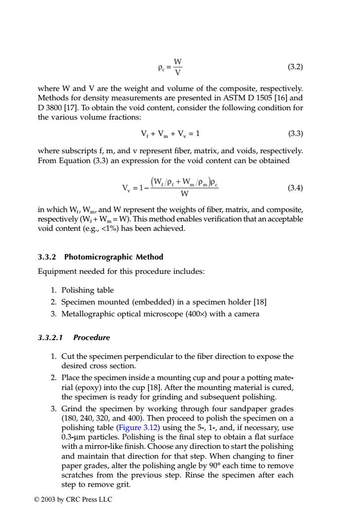
W Pe=V (3.2) where W and V are the weight and volume of the composite,respectively. Methods for density measurements are presented in ASTM D 1505 [16]and D 3800 [17].To obtain the void content,consider the following condition for the various volume fractions: V+V+V,=1 (3.3) where subscripts f,m,and v represent fiber,matrix,and voids,respectively. From Equation(3.3)an expression for the void content can be obtained V.-1-(W:/P:+W-/pm)p. (3.4) W in which Wi,Wm,and W represent the weights of fiber,matrix,and composite, respectively(W:+Wm=W).This method enables verification that an acceptable void content (e.g.,<1%)has been achieved. 3.3.2 Photomicrographic Method Equipment needed for this procedure includes: 1.Polishing table 2.Specimen mounted (embedded)in a specimen holder [18] 3.Metallographic optical microscope(400x)with a camera 3.3.2.1 Procedure 1.Cut the specimen perpendicular to the fiber direction to expose the desired cross section. 2.Place the specimen inside a mounting cup and pour a potting mate- rial (epoxy)into the cup [18].After the mounting material is cured, the specimen is ready for grinding and subsequent polishing. 3.Grind the specimen by working through four sandpaper grades (180,240,320,and 400).Then proceed to polish the specimen on a polishing table(Figure 3.12)using the 5-,1-,and,if necessary,use 0.3-um particles.Polishing is the final step to obtain a flat surface with a mirror-like finish.Choose any direction to start the polishing and maintain that direction for that step.When changing to finer paper grades,alter the polishing angle by 90 each time to remove scratches from the previous step.Rinse the specimen after each step to remove grit. 2003 by CRC Press LLC(3.2) where W and V are the weight and volume of the composite, respectively. Methods for density measurements are presented in ASTM D 1505 [16] and D 3800 [17]. To obtain the void content, consider the following condition for the various volume fractions: Vf + Vm + Vv = 1 (3.3) where subscripts f, m, and v represent fiber, matrix, and voids, respectively. From Equation (3.3) an expression for the void content can be obtained (3.4) in which Wf, Wm, and W represent the weights of fiber, matrix, and composite, respectively (Wf + Wm = W). This method enables verification that an acceptable void content (e.g., <1%) has been achieved. 3.3.2 Photomicrographic Method Equipment needed for this procedure includes: 1. Polishing table 2. Specimen mounted (embedded) in a specimen holder [18] 3. Metallographic optical microscope (400×) with a camera 3.3.2.1 Procedure 1. Cut the specimen perpendicular to the fiber direction to expose the desired cross section. 2. Place the specimen inside a mounting cup and pour a potting material (epoxy) into the cup [18]. After the mounting material is cured, the specimen is ready for grinding and subsequent polishing. 3. Grind the specimen by working through four sandpaper grades (180, 240, 320, and 400). Then proceed to polish the specimen on a polishing table (Figure 3.12) using the 5-, 1-, and, if necessary, use 0.3-µm particles. Polishing is the final step to obtain a flat surface with a mirror-like finish. Choose any direction to start the polishing and maintain that direction for that step. When changing to finer paper grades, alter the polishing angle by 90° each time to remove scratches from the previous step. Rinse the specimen after each step to remove grit. c W V ρ = V W W v W f f m mc = − ( ) + 1 ρ ρρ TX001_ch03_Frame Page 52 Saturday, September 21, 2002 4:51 AM © 2003 by CRC Press LLC