正在加载图片...
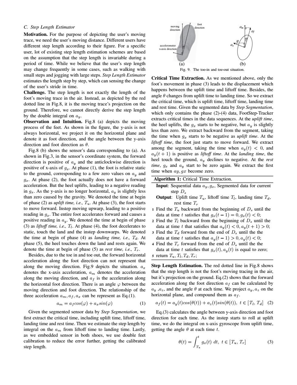
foot C.Step Length Estimator direction Motivation.For the purpose of depicting the user's moving trace,we need the user's moving distance.Different users have different step length according to their figure.For a specific user,lot of existing step length estimation schemes are based on the assumption that the step length is invariable during a period of time.While we believe that the user's step length (a) (b) may change frequently in some cases,such as walking with Fig.9.The toe-in and toe-out situation small steps and jogging with large steps.Step Length Estimator estimates the length step by step,which can sensing the change Critical Time Extraction.As we mentioned above,only the foot's movement in phase (3)leads to the displacement which of the user's stride in time. Challenge.The step length is not exactly the length of the happens between the uplift time and liftoff time.Besides,the foot's moving trace in the air.Instead,as depicted by the red angle 0 changes from uplift time to landing time.So we extract dotted line in Fig.8,it is the moving trace's projection on the the critical time,which is uplift time,liftoff time,landing time ground.Therefore,we cannot directly derive the step length and rest time.Given the segmented data by Step Segmentation, by the double integral on ay. which only contains the phase (2)-(4)data,FootStep-Tracker extracts critical times in the data sequences.At the uplift time. Observation and Intuition.Fig.8 (a)depicts the moving process of the feet.As shown in the figure,the y-axis is not the heel uplifts,the g starts to be negative,but ay is slightly always horizontal,we project it on the horizontal plane and less than zero.We extract backward from the segment,taking denote it as foot direction,and the angle between the y-axis the time when g starts to be negative as uplifi time.At the direction and foot direction as 6. liftoff time,the foot just starts to move forward.We extract Fig.8 (b)shows the sensor's data corresponding to (a).As among the segment,taking the time when ay(t)<0,and shown in Fig.3,in the sensor's coordinate system,the forward ay(t+1)is positive as liftoff time.At the landing time,the direction is positive of ay and the anticlockwise direction is heel touch the ground,ay declines to negative.At the rest positive of x-axis of gr.At phase (1),the foot is relative static time,gr and ay start to be zero again.We extract the first to the ground,corresponding to a few zero values on ay and time when ay,gr become zero. g.At phase (2),the foot actually does not have a forward Algorithm 1:Critical Time Extraction. acceleration.But the heel uplifts,leading to a negative reading Input:Sequential data ay,g,Segmented data for current in gr.As the y-axis is no longer horizontal,ay is slightly less step D. than zero caused by the gravity.We denoted the time at begin Output:Uplift time T,liftoff time T,landing time Ta. of phase(2)as uplifi time,i.e.,Tu.At phase (3),the foot starts rest time T to move forward.Instep moving upwarp,leading to a positive 1 Find the T backward from the beginning of D.until the reading in g.The entire foot accelerates forward and causes a data at time t satisfies that g(t-1)=0,g(t)<0; positive reading in ay We denoted the time at begin of phase 2 Find the Ti backward from the beginning of Ds until the (3)as liftoff time,i.e.,Ti.At phase (4),the foot decelerates to data at time t that satisfies that au(t)<0,au(t+1)>0; static,touch the land and the instep downwarps.We denoted 3 Find the Ta forward from the end of Ds until thethe the time at begin of phase (4)as landing time,i.e..Ta.At data at time t satisfies that a(t-1)>0,a(t)<0; phase(5).the heel touches down the land and rests again.We 4 Find the T forward from the end of D.until the the denote the time at begin of phase (5)as rest time,i.e..T. data at time t satisfies that g(t),a(t)is equal to zero; Besides.due to the toe in and toe out.the forward horizontal 5 return Tu,Ti,Td,Tr: acceleration along the foot direction can not represent that along the moving direction.Fig.9 depicts the situation.a Step Length Estimation.The red dotted line in Fig.8 shows denotes the x-axis acceleration,am denotes the acceleration that the step length is not the foot's moving tracing in the air, along the moving direction,and af is the acceleration along but it's projection on the ground.Eq.(2)shows that the forward the horizontal foot direction.There is an angle between the acceleration along the foot direction af can be calculated by moving direction and foot direction.The relationship of the ay,a=,and the angle at each time.We project ay,a on the three acceleration am,af,ar can be represent as Eq.(1). horizontal plane,and compound them as af. am =afcos(p)+arsin(p) (1) af(t)=ay(t)cos(0(t))+az(t)sin(0(t)),tE[Ti,Tal (2) Given the segmented sensor data by Step Segmentation,we Eq.(3)calculates the angle between y-axis direction and foot first extract the critical time,including uplift time,liftoff time, direction for each time.As the instep starts to roll at uplift landing time and rest time.Then we estimate the step length by time,we do the integral on x-axis gyroscope from uplift time, integral on the am from liftoff time to landing time.Lastly, getting the angle 0 at each time t. as we embedded sensor in both shoes,we use double feet calibration to reduce the error further,getting the calibrated (t)= gz(t)dt,t∈[Tu,T] (3) step length.C. Step Length Estimator Motivation. For the purpose of depicting the user’s moving trace, we need the user’s moving distance. Different users have different step length according to their figure. For a specific user, lot of existing step length estimation schemes are based on the assumption that the step length is invariable during a period of time. While we believe that the user’s step length may change frequently in some cases, such as walking with small steps and jogging with large steps. Step Length Estimator estimates the length step by step, which can sensing the change of the user’s stride in time. Challenge. The step length is not exactly the length of the foot’s moving trace in the air. Instead, as depicted by the red dotted line in Fig.8, it is the moving trace’s projection on the ground. Therefore, we cannot directly derive the step length by the double integral on ay. Observation and Intuition. Fig.8 (a) depicts the moving process of the feet. As shown in the figure, the y-axis is not always horizontal, we project it on the horizontal plane and denote it as foot direction, and the angle between the y-axis direction and foot direction as θ. Fig.8 (b) shows the sensor’s data corresponding to (a). As shown in Fig.3, in the sensor’s coordinate system, the forward direction is positive of ay and the anticlockwise direction is positive of x-axis of gx. At phase (1), the foot is relative static to the ground, corresponding to a few zero values on ay and gx. At phase (2), the foot actually does not have a forward acceleration. But the heel uplifts, leading to a negative reading in gx. As the y-axis is no longer horizontal, ay is slightly less than zero caused by the gravity. We denoted the time at begin of phase (2) as uplift time, i.e., Tu. At phase (3), the foot starts to move forward. Instep moving upwarp, leading to a positive reading in gx. The entire foot accelerates forward and causes a positive reading in ay. We denoted the time at begin of phase (3) as liftoff time, i.e., Tl . At phase (4), the foot decelerates to static, touch the land and the instep downwarps. We denoted the time at begin of phase (4) as landing time, i.e., Td. At phase (5), the heel touches down the land and rests again. We denote the time at begin of phase (5) as rest time, i.e., Tr. Besides, due to the toe in and toe out, the forward horizontal acceleration along the foot direction can not represent that along the moving direction. Fig.9 depicts the situation. ax denotes the x-axis acceleration, am denotes the acceleration along the moving direction, and af is the acceleration along the horizontal foot direction. There is an angle ϕ between the moving direction and foot direction. The relationship of the three acceleration am, af , ax can be represent as Eq.(1). am = af cos(ϕ) + axsin(ϕ) (1) Given the segmented sensor data by Step Segmentation, we first extract the critical time, including uplift time, liftoff time, landing time and rest time. Then we estimate the step length by integral on the am from liftoff time to landing time. Lastly, as we embedded sensor in both shoes, we use double feet calibration to reduce the error further, getting the calibrated step length. moving direction accelerometer x-axis direction foot direction φ (a) φ ax am af φ (b) Fig. 9. The toe-in and toe-out situation. Critical Time Extraction. As we mentioned above, only the foot’s movement in phase (3) leads to the displacement which happens between the uplift time and liftoff time. Besides, the angle θ changes from uplift time to landing time. So we extract the critical time, which is uplift time, liftoff time, landing time and rest time. Given the segmented data by Step Segmentation, which only contains the phase (2)-(4) data, FootStep-Tracker extracts critical times in the data sequences. At the uplift time, the heel uplifts, the gx starts to be negative, but ay is slightly less than zero. We extract backward from the segment, taking the time when gx starts to be negative as uplift time. At the liftoff time, the foot just starts to move forward. We extract among the segment, taking the time when ay(t) < 0, and ay(t + 1) is positive as liftoff time. At the landing time, the heel touch the ground, ay declines to negative. At the rest time, gx and ay start to be zero again. We extract the first time when ay, gx become zero. Algorithm 1: Critical Time Extraction. Input: Sequential data ay, gx, Segmented data for current step Ds Output: Uplift time Tu, liftoff time Tl , landing time Td, rest time Tr 1 Find the Tu backward from the beginning of Ds until the data at time t satisfies that gx(t − 1) = 0, gx(t) < 0; 2 Find the Tl backward from the beginning of Ds until the data at time t that satisfies that ay(t) < 0, ay(t + 1) > 0; 3 Find the Td forward from the end of Ds until the the data at time t satisfies that ay(t − 1) > 0, ay(t) < 0; 4 Find the Tr forward from the end of Ds until the the data at time t satisfies that gx(t), ay(t) is equal to zero; 5 return Tu, Tl , Td, Tr; Step Length Estimation. The red dotted line in Fig.8 shows that the step length is not the foot’s moving tracing in the air, but it’s projection on the ground. Eq.(2) shows that the forward acceleration along the foot direction af can be calculated by ay ,az, and the angle θ at each time. We project ay, az on the horizontal plane, and compound them as af . af (t) = ay(t)cos(θ(t)) + az(t)sin(θ(t)), t ∈ [Tl , Td ] (2) Eq.(3) calculates the angle between y-axis direction and foot direction for each time. As the instep starts to roll at uplift time, we do the integral on x-axis gyroscope from uplift time, getting the angle θ at each time t. θ(t) = Z t Tu gx(t) dt, t ∈ [Tu , Tr ] (3)