正在加载图片...
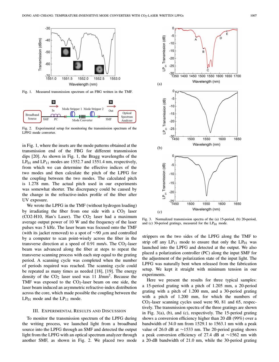
DONG AND CHIANG:TEMPERATURE-INSENSITIVE MODE CONVERTERS WITH CO2-LASER WRITTEN LPFGs 1007 30 0 -5 wgp) 40 -10 50 -15 -20 -60 -25 3 51.0 13501400145015001550160016501700 1551.51552.01552.51553.0 Wavelength(nm) Wavelength(nm) (a) Fig.1. Measured transmission spectrum of an FBG written in the TMF. 0 ▣ 巴 10 In Mode Stripper 1 Mode Stripper 2 Out Broadband Optical -15 Source SMF PC OH Mode Converter SMF Analyzer 20 Fig.2.Experimental setup for monitoring the transmission spectrum of the 25 LPFG mode converter. -3 1450 1500155016001650 in Fig.1,where the insets are the mode patterns obtained at the Wavelength(nm) transmission end of the FBG for different transmission (b) dips [20].As shown in Fig.1,the Bragg wavelengths of the 0 LPoI and LP modes are 1552.7 and 1551.4 nm,respectively, from which we can determine the effective indices of the 马 two modes and then calculate the pitch of the LPFG for -10 the coupling between the two modes.The calculated pitch is 1.278 mm.The actual pitch used in our experiments -15 was somewhat shorter.The discrepancy could be caused by -20 the change in the refractive-index profile of the fiber after UV exposure. - We wrote the LPFG in the TMF(without hydrogen loading) 1450 150015501600 1650 by irradiating the fiber from one side with a CO2 laser Wavelength(nm) (c) (CO2-H10,Han's Laser).The CO2 laser had a maximum Fig.3.Normalized transmission spectra of the (a)15-period,(b)20-period, average output power of 10 W and the frequency of the laser and (c)30-period gratings,measured for the LPo mode. pulses was 5 kHz.The laser beam was focused onto the TMF (with its jacket removed)to a spot of ~90 um and controlled by a computer to scan point-wisely across the fiber in the strippers on the two sides of the LPFG along the TMF to transverse direction at a speed of 0.91 mm/s.The CO2-laser strip off any LPu mode to ensure that only the LPoi was beam was advanced along the fiber at steps to repeat the launched into the LPFG and detected at the output.We also transverse scanning process with each step equal to the grating placed a polarization controller(PC)along the input SMF for period.A scanning cycle was completed when the number the adjustment of the polarization state of the input light.The of periods required was reached.The scanning cycle could LPFG was naturally bent when released from the fabrication be repeated as many times as needed [18],[19].The energy setup.We kept it straight with minimum tension in our density of the CO2 laser used was 11 J/mm2.Because the experiments. TMF was exposed to the CO2-laser beam on one side,the Here we present the results for three typical samples: laser beam induced an asymmetric refractive-index distribution a 15-period grating with a pitch of 1.205 mm,a 20-period across the core,which made possible the coupling between the grating with a pitch of 1.200 mm,and a 30-period grating LPoI mode and the LPi1 mode. with a pitch of 1.200 mm,for which the numbers of CO2-laser scanning cycles used were 90,81 and 65,respec- tively.The transmission spectra of the three gratings are shown III.EXPERIMENTAL RESULTS AND DISCUSSION in Fig.3(a),(b),and(c),respectively.The 15-period grating To monitor the transmission spectrum of the LPFG during shows a conversion efficiency higher than 20 dB(99%)over a the writing process,we launched light from a broadband bandwidth of 34.0 nm from 1529.1 to 1563.1 nm with a peak source into the LPFG through an SMF and detected the output value of 26.0 dB at ~1533 nm.The 20-period grating shows light from the LPFG with an optical spectrum analyzer through a peak conversion efficiency of 27.4 dB at ~1562 nm with another SMF,as shown in Fig.2.We placed two mode a 20-dB bandwidth of 21.0 nm,while the 30-period gratingDONG AND CHIANG: TEMPERATURE-INSENSITIVE MODE CONVERTERS WITH CO2-LASER WRITTEN LPFGs 1007 Fig. 1. Measured transmission spectrum of an FBG written in the TMF. Fig. 2. Experimental setup for monitoring the transmission spectrum of the LPFG mode converter. in Fig. 1, where the insets are the mode patterns obtained at the transmission end of the FBG for different transmission dips [20]. As shown in Fig. 1, the Bragg wavelengths of the LP01 and LP11 modes are 1552.7 and 1551.4 nm, respectively, from which we can determine the effective indices of the two modes and then calculate the pitch of the LPFG for the coupling between the two modes. The calculated pitch is 1.278 mm. The actual pitch used in our experiments was somewhat shorter. The discrepancy could be caused by the change in the refractive-index profile of the fiber after UV exposure. We wrote the LPFG in the TMF (without hydrogen loading) by irradiating the fiber from one side with a CO2 laser (CO2-H10, Han’s Laser). The CO2 laser had a maximum average output power of 10 W and the frequency of the laser pulses was 5 kHz. The laser beam was focused onto the TMF (with its jacket removed) to a spot of ∼90 µm and controlled by a computer to scan point-wisely across the fiber in the transverse direction at a speed of 0.91 mm/s. The CO2-laser beam was advanced along the fiber at steps to repeat the transverse scanning process with each step equal to the grating period. A scanning cycle was completed when the number of periods required was reached. The scanning cycle could be repeated as many times as needed [18], [19]. The energy density of the CO2 laser used was 11 J/mm2. Because the TMF was exposed to the CO2-laser beam on one side, the laser beam induced an asymmetric refractive-index distribution across the core, which made possible the coupling between the LP01 mode and the LP11 mode. III. EXPERIMENTAL RESULTS AND DISCUSSION To monitor the transmission spectrum of the LPFG during the writing process, we launched light from a broadband source into the LPFG through an SMF and detected the output light from the LPFG with an optical spectrum analyzer through another SMF, as shown in Fig. 2. We placed two mode Fig. 3. Normalized transmission spectra of the (a) 15-period, (b) 20-period, and (c) 30-period gratings, measured for the LP01 mode. strippers on the two sides of the LPFG along the TMF to strip off any LP11 mode to ensure that only the LP01 was launched into the LPFG and detected at the output. We also placed a polarization controller (PC) along the input SMF for the adjustment of the polarization state of the input light. The LPFG was naturally bent when released from the fabrication setup. We kept it straight with minimum tension in our experiments. Here we present the results for three typical samples: a 15-period grating with a pitch of 1.205 mm, a 20-period grating with a pitch of 1.200 mm, and a 30-period grating with a pitch of 1.200 mm, for which the numbers of CO2-laser scanning cycles used were 90, 81 and 65, respectively. The transmission spectra of the three gratings are shown in Fig. 3(a), (b), and (c), respectively. The 15-period grating shows a conversion efficiency higher than 20 dB (99%) over a bandwidth of 34.0 nm from 1529.1 to 1563.1 nm with a peak value of 26.0 dB at ∼1533 nm. The 20-period grating shows a peak conversion efficiency of 27.4 dB at ∼1562 nm with a 20-dB bandwidth of 21.0 nm, while the 30-period grating