正在加载图片...
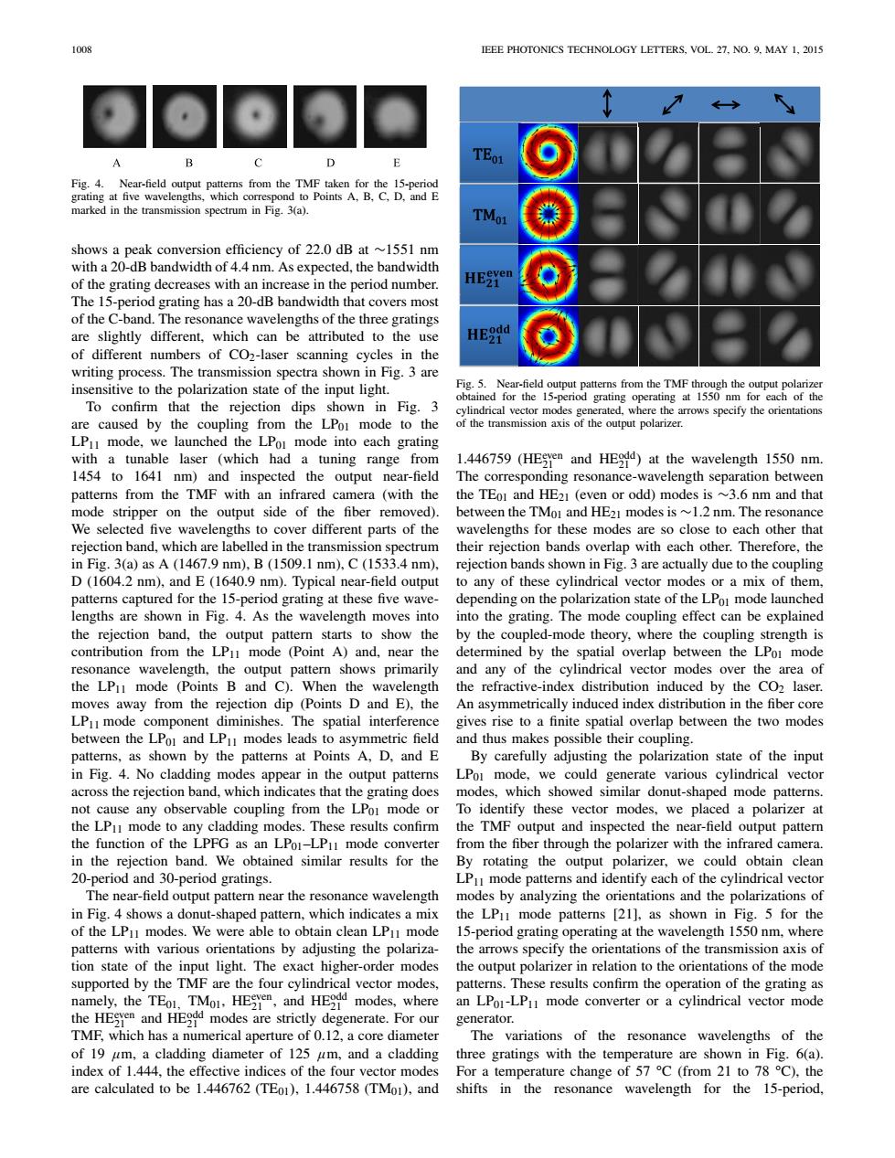
1008 IEEE PHOTONICS TECHNOLOGY LETTERS,VOL.27.NO.9.MAY 1,2015 可O D TEo1 Fig.4.Near-field output patters from the TMF taken for the 15-period grating at five wavelengths,which correspond to Points A,B,C.D,and E marked in the transmission spectrum in Fig.3(a). TMoi shows a peak conversion efficiency of 22.0 dB at ~1551 nm with a 20-dB bandwidth of 4.4 nm.As expected,the bandwidth of the grating decreases with an increase in the period number. The 15-period grating has a 20-dB bandwidth that covers most of the C-band.The resonance wavelengths of the three gratings are slightly different,which can be attributed to the use of different numbers of CO2-laser scanning cycles in the writing process.The transmission spectra shown in Fig.3 are insensitive to the polarization state of the input light. Fig.5.Near-field output patterns from the TMF through the output polarizer obtained for the 15-period grating operating at 1550 nm for each of the To confirm that the rejection dips shown in Fig.3 cylindrical vector modes generated,where the arrows specify the orientations are caused by the coupling from the LPoi mode to the of the transmission axis of the output polarizer. LPI mode,we launched the LPor mode into each grating with a tunable laser (which had a tuning range from 1.446759 (HESyen and HEdd)at the wavelength 1550 nm. 1454 to 1641 nm)and inspected the output near-field The corresponding resonance-wavelength separation between patterns from the TMF with an infrared camera(with the the TEor and HE21 (even or odd)modes is ~3.6 nm and that mode stripper on the output side of the fiber removed). between the TMoi and HE21 modes is ~1.2 nm.The resonance We selected five wavelengths to cover different parts of the wavelengths for these modes are so close to each other that rejection band,which are labelled in the transmission spectrum their rejection bands overlap with each other.Therefore,the in Fig.3(a)as A (1467.9 nm),B(1509.1 nm),C(1533.4 nm),rejection bands shown in Fig.3 are actually due to the coupling D (1604.2 nm),and E(1640.9 nm).Typical near-field output to any of these cylindrical vector modes or a mix of them, patterns captured for the 15-period grating at these five wave-depending on the polarization state of the LPo mode launched lengths are shown in Fig.4.As the wavelength moves into into the grating.The mode coupling effect can be explained the rejection band,the output pattern starts to show the by the coupled-mode theory,where the coupling strength is contribution from the LPu mode (Point A)and,near the determined by the spatial overlap between the LPol mode resonance wavelength,the output pattern shows primarily and any of the cylindrical vector modes over the area of the LPu mode (Points B and C).When the wavelength the refractive-index distribution induced by the CO2 laser. moves away from the rejection dip (Points D and E),the An asymmetrically induced index distribution in the fiber core LPuI mode component diminishes.The spatial interference gives rise to a finite spatial overlap between the two modes between the LPoI and LPu modes leads to asymmetric field and thus makes possible their coupling. patterns,as shown by the patterns at Points A,D,and E By carefully adjusting the polarization state of the input in Fig.4.No cladding modes appear in the output patterns LPor mode,we could generate various cylindrical vector across the rejection band,which indicates that the grating does modes,which showed similar donut-shaped mode patterns. not cause any observable coupling from the LPor mode or To identify these vector modes,we placed a polarizer at the LP]mode to any cladding modes.These results confirm the TMF output and inspected the near-field output pattern the function of the LPFG as an LPoI-LPu mode converter from the fiber through the polarizer with the infrared camera. in the rejection band.We obtained similar results for the By rotating the output polarizer,we could obtain clean 20-period and 30-period gratings. LP mode patterns and identify each of the cylindrical vector The near-field output pattern near the resonance wavelength modes by analyzing the orientations and the polarizations of in Fig.4 shows a donut-shaped pattern,which indicates a mix the LP1 mode patterns [21],as shown in Fig.5 for the of the LPu modes.We were able to obtain clean LPI mode 15-period grating operating at the wavelength 1550 nm,where patterns with various orientations by adjusting the polariza- the arrows specify the orientations of the transmission axis of tion state of the input light.The exact higher-order modes the output polarizer in relation to the orientations of the mode supported by the TMF are the four cylindrical vector modes,patterns.These results confirm the operation of the grating as namely,the TEo.TMo.HESYen,and HEdd modes,where an LPoI-LP mode converter or a cylindrical vector mode the HESyen and HEdd modes are strictly degenerate.For our generator. TMF,which has a numerical aperture of 0.12,a core diameter The variations of the resonance wavelengths of the of 19 um,a cladding diameter of 125 um,and a cladding three gratings with the temperature are shown in Fig.6(a) index of 1.444,the effective indices of the four vector modes For a temperature change of 57 C(from 21 to 78 C),the are calculated to be 1.446762 (TEo1),1.446758 (TMo1),and shifts in the resonance wavelength for the 15-period,1008 IEEE PHOTONICS TECHNOLOGY LETTERS, VOL. 27, NO. 9, MAY 1, 2015 Fig. 4. Near-field output patterns from the TMF taken for the 15-period grating at five wavelengths, which correspond to Points A, B, C, D, and E marked in the transmission spectrum in Fig. 3(a). shows a peak conversion efficiency of 22.0 dB at ∼1551 nm with a 20-dB bandwidth of 4.4 nm. As expected, the bandwidth of the grating decreases with an increase in the period number. The 15-period grating has a 20-dB bandwidth that covers most of the C-band. The resonance wavelengths of the three gratings are slightly different, which can be attributed to the use of different numbers of CO2-laser scanning cycles in the writing process. The transmission spectra shown in Fig. 3 are insensitive to the polarization state of the input light. To confirm that the rejection dips shown in Fig. 3 are caused by the coupling from the LP01 mode to the LP11 mode, we launched the LP01 mode into each grating with a tunable laser (which had a tuning range from 1454 to 1641 nm) and inspected the output near-field patterns from the TMF with an infrared camera (with the mode stripper on the output side of the fiber removed). We selected five wavelengths to cover different parts of the rejection band, which are labelled in the transmission spectrum in Fig. 3(a) as A (1467.9 nm), B (1509.1 nm), C (1533.4 nm), D (1604.2 nm), and E (1640.9 nm). Typical near-field output patterns captured for the 15-period grating at these five wavelengths are shown in Fig. 4. As the wavelength moves into the rejection band, the output pattern starts to show the contribution from the LP11 mode (Point A) and, near the resonance wavelength, the output pattern shows primarily the LP11 mode (Points B and C). When the wavelength moves away from the rejection dip (Points D and E), the LP11 mode component diminishes. The spatial interference between the LP01 and LP11 modes leads to asymmetric field patterns, as shown by the patterns at Points A, D, and E in Fig. 4. No cladding modes appear in the output patterns across the rejection band, which indicates that the grating does not cause any observable coupling from the LP01 mode or the LP11 mode to any cladding modes. These results confirm the function of the LPFG as an LP01–LP11 mode converter in the rejection band. We obtained similar results for the 20-period and 30-period gratings. The near-field output pattern near the resonance wavelength in Fig. 4 shows a donut-shaped pattern, which indicates a mix of the LP11 modes. We were able to obtain clean LP11 mode patterns with various orientations by adjusting the polarization state of the input light. The exact higher-order modes supported by the TMF are the four cylindrical vector modes, namely, the TE01, TM01, HEeven 21 , and HEodd 21 modes, where the HEeven 21 and HEodd 21 modes are strictly degenerate. For our TMF, which has a numerical aperture of 0.12, a core diameter of 19 µm, a cladding diameter of 125 µm, and a cladding index of 1.444, the effective indices of the four vector modes are calculated to be 1.446762 (TE01), 1.446758 (TM01), and Fig. 5. Near-field output patterns from the TMF through the output polarizer obtained for the 15-period grating operating at 1550 nm for each of the cylindrical vector modes generated, where the arrows specify the orientations of the transmission axis of the output polarizer. 1.446759 (HEeven 21 and HEodd 21 ) at the wavelength 1550 nm. The corresponding resonance-wavelength separation between the TE01 and HE21 (even or odd) modes is ∼3.6 nm and that between the TM01 and HE21 modes is ∼1.2 nm. The resonance wavelengths for these modes are so close to each other that their rejection bands overlap with each other. Therefore, the rejection bands shown in Fig. 3 are actually due to the coupling to any of these cylindrical vector modes or a mix of them, depending on the polarization state of the LP01 mode launched into the grating. The mode coupling effect can be explained by the coupled-mode theory, where the coupling strength is determined by the spatial overlap between the LP01 mode and any of the cylindrical vector modes over the area of the refractive-index distribution induced by the CO2 laser. An asymmetrically induced index distribution in the fiber core gives rise to a finite spatial overlap between the two modes and thus makes possible their coupling. By carefully adjusting the polarization state of the input LP01 mode, we could generate various cylindrical vector modes, which showed similar donut-shaped mode patterns. To identify these vector modes, we placed a polarizer at the TMF output and inspected the near-field output pattern from the fiber through the polarizer with the infrared camera. By rotating the output polarizer, we could obtain clean LP11 mode patterns and identify each of the cylindrical vector modes by analyzing the orientations and the polarizations of the LP11 mode patterns [21], as shown in Fig. 5 for the 15-period grating operating at the wavelength 1550 nm, where the arrows specify the orientations of the transmission axis of the output polarizer in relation to the orientations of the mode patterns. These results confirm the operation of the grating as an LP01-LP11 mode converter or a cylindrical vector mode generator. The variations of the resonance wavelengths of the three gratings with the temperature are shown in Fig. 6(a). For a temperature change of 57 °C (from 21 to 78 °C), the shifts in the resonance wavelength for the 15-period