正在加载图片...
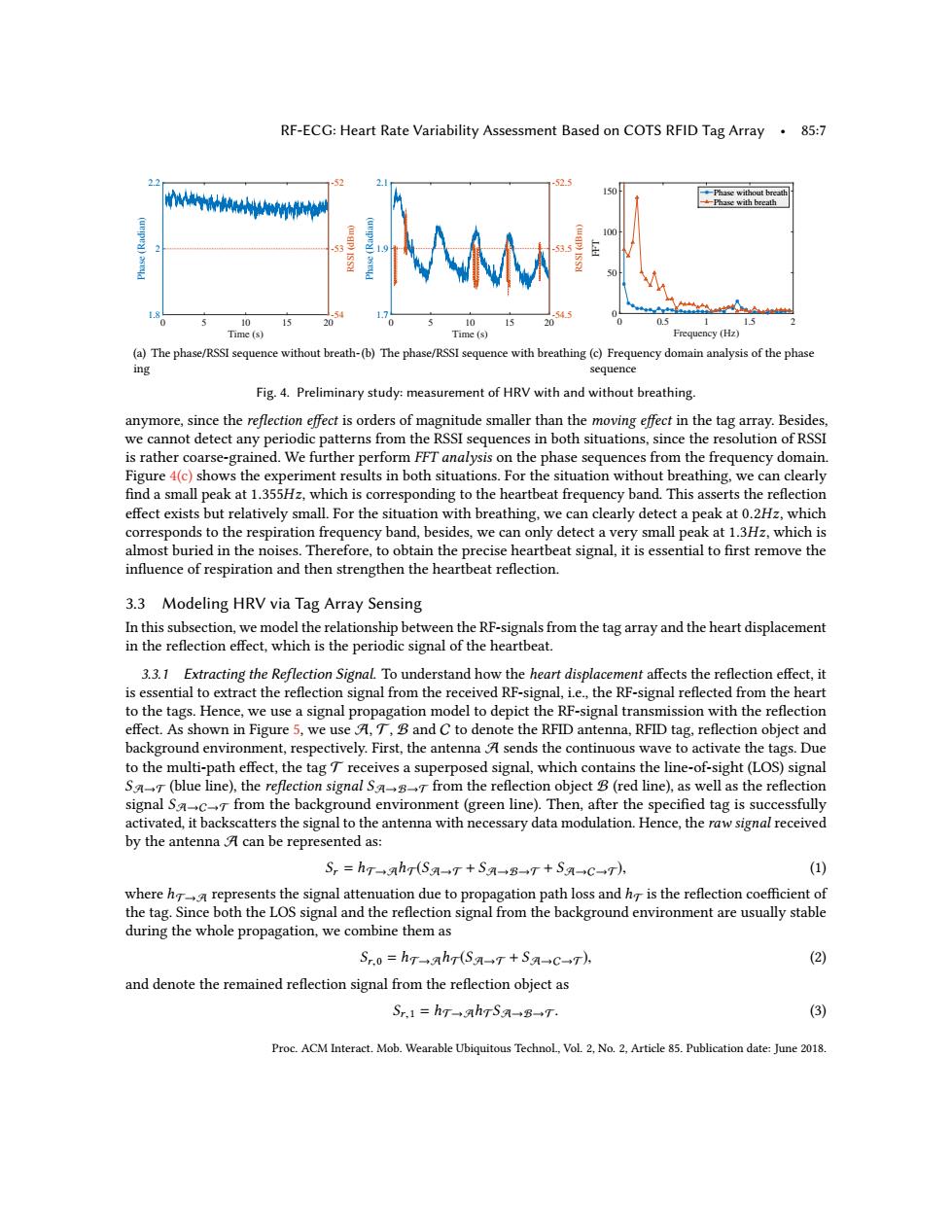
RF-ECG:Heart Rate Variability Assessment Based on COTS RFID Tag Array.85:7 2.2 -52 -525 10 a的人心 10 10 15 Time(s) Time(s) Frequency(Hz) (a)The phase/RSSI sequence without breath-(b)The phase/RSSI sequence with breathing(c)Frequency domain analysis of the phase ing sequence Fig.4.Preliminary study:measurement of HRV with and without breathing. anymore,since the reflection effect is orders of magnitude smaller than the moving effect in the tag array.Besides, we cannot detect any periodic patterns from the RSSI sequences in both situations,since the resolution of RSSI is rather coarse-grained.We further perform FFT analysis on the phase sequences from the frequency domain. Figure 4(c)shows the experiment results in both situations.For the situation without breathing,we can clearly find a small peak at 1.355Hz,which is corresponding to the heartbeat frequency band.This asserts the reflection effect exists but relatively small.For the situation with breathing,we can clearly detect a peak at 0.2Hz,which corresponds to the respiration frequency band,besides,we can only detect a very small peak at 1.3Hz,which is almost buried in the noises.Therefore,to obtain the precise heartbeat signal,it is essential to first remove the influence of respiration and then strengthen the heartbeat reflection. 3.3 Modeling HRV via Tag Array Sensing In this subsection,we model the relationship between the RF-signals from the tag array and the heart displacement in the reflection effect,which is the periodic signal of the heartbeat. 3.3.1 Extracting the Reflection Signal.To understand how the heart displacement affects the reflection effect,it is essential to extract the reflection signal from the received RF-signal,i.e.,the RF-signal reflected from the heart to the tags.Hence,we use a signal propagation model to depict the RF-signal transmission with the reflection effect.As shown in Figure 5,we use A,T,B and C to denote the RFID antenna,RFID tag,reflection object and background environment,respectively.First,the antenna A sends the continuous wave to activate the tags.Due to the multi-path effect,the tagT receives a superposed signal,which contains the line-of-sight(LOS)signal SaT(blue line),the reflection signal Sa from the reflection object B(red line),as well as the reflection signal Sac from the background environment (green line).Then,after the specified tag is successfully activated,it backscatters the signal to the antenna with necessary data modulation.Hence,the raw signal received by the antenna A can be represented as: S,=hT+ah(S-+T+SA-B-T+S领-→+C→T), (1) where h represents the signal attenuation due to propagation path loss and h is the reflection coefficient of the tag.Since both the LOS signal and the reflection signal from the background environment are usually stable during the whole propagation,we combine them as Sr.0=hTah(Sa-T+SA→c→T) (2) and denote the remained reflection signal from the reflection object as Sr.1=hT-→ahrSa→B-→T (3) Proc.ACM Interact.Mob.Wearable Ubiquitous Technol,Vol.2,No.2,Article 85.Publication date:June 2018.RF-ECG: Heart Rate Variability Assessment Based on COTS RFID Tag Array • 85:7 Time (s) 0 5 10 15 20 Phase (Radian) 1.8 2 2.2 RSSI (dBm) -54 -53 -52 (a) The phase/RSSI sequence without breathing Time (s) 0 5 10 15 20 Phase (Radian) 1.7 1.9 2.1 RSSI (dBm) -54.5 -53.5 -52.5 (b) The phase/RSSI sequence with breathing Frequency (Hz) 0 0.5 1 1.5 2 FFT 0 50 100 150 Phase without breath Phase with breath (c) Frequency domain analysis of the phase sequence Fig. 4. Preliminary study: measurement of HRV with and without breathing. anymore, since the reflection effect is orders of magnitude smaller than the moving effect in the tag array. Besides, we cannot detect any periodic patterns from the RSSI sequences in both situations, since the resolution of RSSI is rather coarse-grained. We further perform FFT analysis on the phase sequences from the frequency domain. Figure 4(c) shows the experiment results in both situations. For the situation without breathing, we can clearly find a small peak at 1.355Hz, which is corresponding to the heartbeat frequency band. This asserts the reflection effect exists but relatively small. For the situation with breathing, we can clearly detect a peak at 0.2Hz, which corresponds to the respiration frequency band, besides, we can only detect a very small peak at 1.3Hz, which is almost buried in the noises. Therefore, to obtain the precise heartbeat signal, it is essential to first remove the influence of respiration and then strengthen the heartbeat reflection. 3.3 Modeling HRV via Tag Array Sensing In this subsection, we model the relationship between the RF-signals from the tag array and the heart displacement in the reflection effect, which is the periodic signal of the heartbeat. 3.3.1 Extracting the Reflection Signal. To understand how the heart displacement affects the reflection effect, it is essential to extract the reflection signal from the received RF-signal, i.e., the RF-signal reflected from the heart to the tags. Hence, we use a signal propagation model to depict the RF-signal transmission with the reflection effect. As shown in Figure 5, we use A, T, B and C to denote the RFID antenna, RFID tag, reflection object and background environment, respectively. First, the antenna A sends the continuous wave to activate the tags. Due to the multi-path effect, the tag T receives a superposed signal, which contains the line-of-sight (LOS) signal SA→T (blue line), the reflection signal SA→B→T from the reflection object B (red line), as well as the reflection signal SA→C→T from the background environment (green line). Then, after the specified tag is successfully activated, it backscatters the signal to the antenna with necessary data modulation. Hence, the raw signal received by the antenna A can be represented as: Sr = hT→AhT(SA→T + SA→B→T + SA→C→T), (1) where hT→A represents the signal attenuation due to propagation path loss and hT is the reflection coefficient of the tag. Since both the LOS signal and the reflection signal from the background environment are usually stable during the whole propagation, we combine them as Sr,0 = hT→AhT(SA→T + SA→C→T), (2) and denote the remained reflection signal from the reflection object as Sr,1 = hT→AhTSA→B→T. (3) Proc. ACM Interact. Mob. Wearable Ubiquitous Technol., Vol. 2, No. 2, Article 85. Publication date: June 2018