正在加载图片...
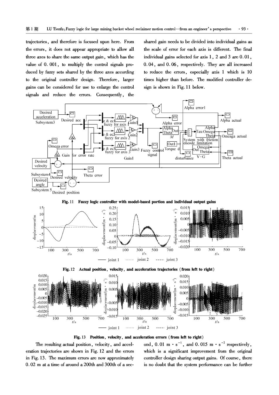
1 LU Tienfu:Fuzzy logic for large mining bucket wheel reclaimer motion control-from an engineer's perspective ·93 trajectories,and therefore is focused upon here.From shared gain needs to be divided into individual gains as the errors,it does not appear appropriate to allow all the scale of error for each axis is different.The final three axes to share the same output gain,which has the individual gains selected for axis 1,2 and 3 are 0.01, value of 0.001,to multiply the control signals pro- 0.04,and 0.06,respectively.They are all increased duced by fuzzy sets shared by the three axes according to reduce the errors,especially axis 1 which is 10 to the original controller design.Therefore,larger times higher than before.The modified controller de- gains can be considered for use to enlarge the control sign is shown in Fig.11 below. signals and reduce the errors.Consequently,the Alpha errorl Desired acceleration +回 回 R Subsystem3 Desired acc Alpha actual for axi ain Alpha error Alpha Tau Omega 回 K fuzzy for axis M Theta Omeaga actual System with friction Out1 encode limitation Omega error fuzzy for axis 3Gain3 Fuzzy control Torque d Omega Theta. Gain or error rate signal 回 Gainl disturbance V+G Theta actual Desired velocity 回 Subsystem Desired velocity Theta error Desired angle 同 Subsystem 5 Desired posltion Fig.11 Fuzzy logic controller with model-based portion and individual output gains 15 0.25 0.015r 0.20 0.010 5 0.15 0.005 0.10 0.05 -0.005 A -0.01C -10 -0.05 -0.015 -15 -0.10 -0.020 100 300 500 700 100 300 500 700 100 300 500 700 tis tls tis joint I joint 2 ---…joint3 Fg.12 Actual position,velocity,and acceleration trajectories from left to right) 0.020 0.015 0.020 0.059 0.010 0.010 0.015 0.005 0.010 J 0.005 s-0005 0 -0.010 -0.05 0.005 克-0.015 -0.020 元-0.010 -0.010 0.025 0.015 100 300 500 700-0.0154 100 300 500700 100 300 500 700 -joint I …joint2 ----.joint 3 Fig.13 Position,velocity,and acceleration errors (from left to right) The resulting actual position,velocity,and accel-ond,0.01 m.s-,and 0.015 m.s-2respectively, eration trajectories are shown in Fig.12 and the errors which is a significant improvement from the original in Fig.13.The maximum errors are now approximately controller design sharing output gains.Of course,there 0.02 m at a time of around a 200th and 300th of a sec- is no doubt that the system performance can be further