第6卷第1期 智能系统学报 Vol.6 No.1 2011年2月 CAAI Transactions on Intelligent Systems Feh.2011 doi:10.3969/j.iasn.1673-4785.2011.01.012 Fuzzy logic for large mining bucket wheel reclaimer motion control-from an engineer's perspective LU Tienfu (School of Mechanical Engineering,University of Adelaide,North Terrace Adelaide,South Australia SA 5005,Australia) Abstract:The bucket wheel reclaimer(BWR)is a key piece of equipment which has been widely used for stacking and reclai- ming bulk materials (i.e.iron ore and coal)in places such as ports,iron-steel plants,coal storage areas,and power stations from stockpiles.BWRs are very large in size,heavy in weight,expensive in price,and slow in motion.There are many challen- ges in attempting to automatically control their motion to accurately follow the required trajectories involving uncertain parameters from factors such as friction,turbulent wind,its own dynamics,and encoder limitations.As BWRs are always heavily engaged in production and cannot be spared very long for motion control studies and associated developments,a BWR model and simulation environment closely resembling real life conditions would be beneficial.The following research focused mainly on the implementa- tion of fuzzy logic to a BWR motion control from an engineer's perspective.First,the modeling of a BWR including partially known parameters such as friction force and turbulence to the system was presented.This was then followed by the design of a fuzzy logic-based control built on a model-based control loop.The investigation provides engineers with an example of applying fuzzy logic in a model based approach to properly control the motion of a large BWR following defined trajectories,as well as to show possible ways of further improving the controller performance.The result indicates that fuzzy logic can be applied easily by engineers to overcome most motion control issues involving a large BWR. Keywords:bucket wheel reclaimer;modeling;simulation;motion control;fuzzy logic CLC Number:TP273.4 Document code:A Article ID:1673-4785(2011)01-0085-10 The Australian mineral industry has played an im- issues which have arisen due to the uncertainties portant role in Australia's economy for years.A snap-caused by the insufficient knowledge and modeling er- shot shows that it represented 26%of Australian cap- rors of the bucket wheel reclaimer (BWR)that are ital investment,8%of total national GDP,and 40% normally associated with stacking and reclaiming stock- of total trade in the 2006-2007 fiscal year.The in- pilesin port areas. dustry is mostly located in rural and remote Australia, Anyone who knows the field would agree that and contributes vast sums to the taxation and royalty there are a lot more areas regarding the operations asso- revenues of the Australian Governments. ciated with BWRs which could be further developed, The mining industry is one of the most important including improving the efficiency of BWR motion con- export industries in Australia.Mining covers a broad trol.Nevertheless,stockpiles and BWRs within a spectrum of activities,from exploring and identifying stockyard are always heavily engaged and stretched to new ore bodies such as coal,to processing,transporta- production limits.As they often cannot be spared for tion,and exporting.Before solid bulk materials such the required time period of research and development as metal ores are exported,they are normally stock- in order to improve operation efficiencies,alternatives piled at ports while waiting to be reclaimed according are required.One of the choices is simulation.By to the desired quality and quantity combinations,and properly reflecting the physics in areas such as uncer- subsequently loaded to ships. tainty in computer simulation environments,research The presented work concerns the motion control and development can be carried out without interrup- Received Date:2010-09-25. ting the production operation of real BWRs until the Corresponding Author:LU Tienfu.E-mail:tien-fu.luadelaide.edu.u very late stages involving fine tuning and implementa- tions
86 智能系统学报 第6卷 From the perspective of controlling the motion of as well as the imperfect knowledge of the system (un- such large machinery (BWR in this case),one of the certainties),through the modelling of friction forces, key challenges lies in the imperfect knowledge about encoder limitations,and unexpected disturbances as the system.It is not difficult to derive correct kinemat- the part of the system which is unknown to the control- ics (forward and inverse),but it is extremely difficult ler.Section II presents fuzzy logic that will be used to to obtain accurate dynamics which include all the deal with the modelling uncertainties and errors.In effects acting on the large machine such as frictional section II controller design using fuzzy logic on top of and environmental forces (i.e.impact forces which in- a model-based portion is presented.Section IV pres- teract with the environment and turbulent forces caused ents trajectory generation,and Section V gives simula- by wind).Rather than using the real BWR which is tion results and discussions.Finally,the conclusions heavily engaged in production,this study first develops are presented in Section VI. a simulation model to reflect the imperfect knowledge of 1 Bucket wheel reclaimer modeling the system,especially in relation to dynamics.Then based on such a model,a fuzzy logic based controller Fig.1 below shows the simplified mining operation is developed to follow the designed motion trajectory. process regarding the flow of iron ores.It depicts which To model a typical BWR,its kinematics and dy- two stages of bulk materials are stockpiled and subse- namics which describe the behaviours and motions of quently reclaimed,in this case using BWRs. the BWR are essential.So far,very few studies have Dumping Reclaiming been published in the public domain for BWR model- Rail to to Shipping stacking shiploading/ ling.In 1997,Choi et alt2.solved the inverse kine- matics of a BWR using a false position method.The extracted contour lines which resulted from a 3-dimen- Stockpile Queue of Stockpile Queue of surge ore cars surge vessels tional range finder were viewed as reclaiming patches Fig.1 Flow of bulk materials on which the ore can be extracted.The BWR was trea- BWRs have been widely adopted in mining indus- ted as 4 degrees of freedom robotic manipulator posses- try for stacking and reclaiming stockpiles as shown in sing redundancy in its kinematics.Furthermore,the Fig.2.To this point,BWRs are still mostly manually inverse kinematics problem of a BWR was extensively investigated by Choi et al.in 199913 and Hong and operatedis,remotely operated,orautomted to follow Choi in 2000141.The inverse kinematics problem was simple predefined trajectory patterns with no flexibility of real-time automatic trajectory change when needed. solved for both whole stockpile reclaiming and layer re- With bulk handling facilities stretched to mechanical claiming.The key focus of those studies was to find an limits in order to meet market demands,the efficiency optimal landing point for reclaiming to prevent overload and motion accuracy gained through improved control which occurrs when the buckets dig ore deeper than the will be of great benefit1. prescribed scooping depth.The proposed automatic landing algorithm successfully implemented for the re- claimer in Kwangyang Steelworks,Korea.Positional errors of 20 cm resulted between the trajectory of the buckets and the surface of the pile.Error boundaries were said to be acceptable because the bucket length and width were about 80 and 40 cm respectively.Nev- ertheless,there was no similar modelling work presen- ted in the study to reflect a real BWR model for con- Fig.2 KRUPP bucket wheel reclaimer troller design and related research as demonstrated by the presented study. From a modeling perspective,a typical BWR can In this paper,Section I presents the modelling of normally be treated as having 3 degrees of freedom ex- a typical BWR including its kinematics and dynamics, cluding the rotating bucket wheel.The first degree of
第1期LU Tienfu:Fuz☒logic for large mining bucket wheel reclaimer motion contro--from an engineer's perspective·87· freedom (axis 1)comes from a linear track located at As the kinematics and dynamics of a BWR have the bottom of the BWR,as shown in Fig.3.This pris- been derived and presented,in the following section, matic axis is represented by a rectangular box with a the final equations are extracted and listed.The details black dot in it.The linear track allows the BWR to of the derivations can be found in the author's previ- move linearly and therefore is a prismatic joint using ous work[3.5] robotic terminology.The second degree of freedom Based on the assumption that the BWR studied (axis 2)comes from the luff motion which swings the here has the parameters listed in Table 1 and joint lim- boom.This axis is represented by a vertical line point- its listed in Equ.(1),which are subject to changes ing up with an arrow.The third degree of freedom (ax- since different BWRs will have different parameters, is 3)comes from the slew motion which rotates the the following kinematics and dynamics were derived. boom up and down.This axis is represented by a circle Table 1 Parameters of the BWR with a black dot in it.Therefore,a typical BWR can L L be treated as a PRR (prismatic-revolute-revolute)ro- botic arm. 6 5 5 50 ↑Axis2,revolute r-25m≤d1≤25m, -90°<02<90°, (1) Axis 3,revolute l-15°<03<15°, Axis 1,prismatic pointing out of the paper 1)BWR kinematics. The BWR's forward kinematics are shown Fig.3 A drawing of a bucket wheel reclaimer on the left and a stockpile on the right in Equ.(2). sin 02sin 0 cos 02 sin 02cos 0 -8in02(50cos03+5) T -C0883 0 -sin 03 -50sin03-11 (2) cos 0,sin 0 sin 0, c0802c0803 50cos 02cos 03 +5cos 02+d 0 0 0 1 The BWR's inverse kinematics are shown in With reference to Fig.4,0;is the angle between Equ.(3)below: X-I and X;measured about ZL;is the distance from Z 6,=Aan2[(-y-11),(√502-(y+11))], to Z measure along Xd is the distance from X to &=4sin(50eni6+5, X:measured along Z:. With the given desired (x,y,z)coordinate for d1=z-50cos02c0803-5cos02: (3) the CP (centre point of the bucket wheel)to reach, the sequence of solving the inverse kinematics starts Axis 3:revolute from 03 and finishes at obtaining d. Z. X 2)BWR dynamics. CP As the real structure of the BWR is complicated as can be seen in Fig.2 and not readily available for this study,the mass distributions of the linkages are thus Axis 2:revolute simplified and assumed to be point masses which should be still appropriate for the construction of a rea- Axis 1:prismatic sonable model.The locations of the point masses are detailed in the author's previous investigation.The general joint state space dynamic equation can be ex- Fig.4 BWR motion axes pressed as:
·88· 智能系统学报 第6卷 x=M(0)0+V(0,0)+G(0). The more complete dynamic model becomes: Where M is a 3 x3 mass matrix,V is a 3 x 1 vector for r=M(0)0+V0,0)+G(0)+F(0,0). Corilois/Centrifugal forces and G is a 3 x1 gravity vec- 4)Modeling of encoders. tor.The equations for the mass matrix and vectors are Encoders are normally attached to the joints to re- listed below. cord their motions (i.e.how many degrees the joint rm(1,1) 0 m(1,3)1 has rotated).However,they are limited by their reso- M(0)= 0m(2,2)m(2,3) lutions to interpret the motion of joints.As the encoder m(3,1)m(3,2)m(3,3) output is discrete,there will be errors caused by reso- Wher lution limitation.In the presented study,quantiser m(1,1)-250+25m(1+10cos64)+ blocks using Simulink are incorporated to simulate the discrete nature and errors resulting from the limited 625m3cos203, resolutions of encoders. m1,3》=m(3,1)=ia,(5m+10%,+ Assuming all the position encoders consisting of the 2 4 and 3(luff and slew)joints have 4 096 bits 50m3c0s03), per revolution,the long travel encoder is directly cou- m(2,2)=625m3, pled to a non-drive bogie wheel axel with a wheel circ- m(2,3)=m(3,2)=-25m3sin03cos02, umference about 2 m.Thus,the resolution is 360 (de- m(3,3)=m1+m2+m3, grees)/4096=0.087 89 degrees,which is equivalent r(1,1)7 to 0.001 533 4 radians.The quantization intervals for V(0,0)= (2,1) the three encoders are therefore set at 0.001 533 4 for LV(3,1) the presented study. Where, 5)Modeling of disturbances. V(1,1)=-25m30203sin03(1+5cos03), In order to model more realistically,a vector with V(2,1)=125m35sin03(1+5cos03), a random disturbance force/torque was applied at all V(3,1)=-2.5m25cos02-5m3cos02- three joints,Ta,which have the random values be- 25m305co802cos03+50m30203sin028in03- tween 100 and -100(kg for prismatic joint and kg-m 25m33c0802c0s03, for revolute joints)with a mean value of zero while act- 0 ing to disturb the system is introduced into the control G(0)= 25magcos 03 system.This external noise is introduced to partially 0 cover the combined influences of modelling inaccura- 3)Modeling of friction forces. cies caused by factors such as simplifying the dynam- The dynamic equations derived above do not cover ics,un-modelled bucket wheels,and scooped materi- all the forces acting on the BWR,including friction.In als in the bucket wheels. order to create a simulation environment that can reflect the imperfect knowledge of the system,it is important 2 Fuzzy logic to model friction forces such as disturbances and errors It is always difficult for an expert to represent the coming from encoders as the parts of the system that required knowledge to solve an engineering problem u- are unknown to the controller.There are two friction sing vague and ambiguous computer terms until certain forces to be modelled,viscous friction and Coulomb artificial techniques such as fuzzy logic are available. friction.Nevertheless,in this study,a vector of fric- From an engineer's perspective,using engineering tion coefficients for three joints is set as the gain, common sense in vague and ambiguous terms to solve [0.05,0.05,0.05]which is multiplied by the joint engineering problems is intuitive and even preferred in velocities to generate friction forces similar to viscous many cases.For example,to prevent a motor from run- friction forces.These gains can later be changed for ning too hot,it is much easier to describe the control more accurate results or even replaced by the combina- actions required in vague and ambiguous terms,such tion of Coulomb and viscous friction forces. as"if the motor is overheating,you must slow it down

1LU Tienfu:Fuzzy logic for large mining bucket wheel reclaimer motion control-from an engineer's perspective89. than set conditions in crisp numbers ing problems,normally not enough attention is paid to Fuzzy logic is multi-valued logic.It allows any the complicated mathematics behind the user interface degree of value from 0 to 1 to be assigned in a fuzzy to perform such fuzzification and defuzzification.In- set,such as gray instead of black or white.This is dif- stead,focus is given to choosing one of the readily a- ferent from crisp logic,where given items are either vailable software programs that most likely share a sim- members of a definite set or they are not.It is therefore ilar graphical user interface,similar ways of entering possible to have a reasoning system which makes deci-fuzzy logic rules,and similar methods of setting up sions by combing set membership distributions.This membership sets based on his/her preferences.Of gives great flexibility in making decisions based upon course,ultimately,the chosen software will still need degrees of truth when facing uncertainties that are too to deliver satisfactory results. difficult or cumbersome to be defined using crisp num- Depending on the nature of the problems to be re- bers.However,there must be a set of rules,where the solved using fuzzy logic,engineers will need to look in- conjunction"and"calls for the minimum membership to aspects of setting up the fuzzy logic parameters in- of the topic being considered to yield an output mem-cluding numbers of input/output,fuzzy logic rules, bership value for decision-making purposes.As a range of membership sets,and input/output scaling. result,fuzzy logic has been widely adopted and applied These factors will be detailed in the next section. for the entire span of engineering applications and 3 Controller design products ranging from manufacturing machinery to do- mestic appliances (i.e.the washing machine). The size of a BWR is large (i.e.50 meter long Engineers normally are short of time in dealing boom which is the length of one link)and therefore it with one given problem.They need to effectively solve normally moves slowly.In the author's previous work, the given problem and move on as soon as possible as a model-based controller was developed.However,the there are always plenty problems waiting to be re- performance of a model-based controller is indeed sen- solved.Many engineers would wish to have more time sitive to modeling errors and unexpected disturbances to conduct thorough studies and investigations for the in addition to the need of laboriously finding appropri- best solutions before moving on,but such a wish is not ate gains.Hence,fuzzy logic is adopted and imple- normally granted. mented to deal with the modeling errors and uncertain- When solving problems concerning uncertainties ties on top of the model based portion,which is limited having values other than false and true (0 and 1), by the lack of knowledge about the system,to improve fuzzy logic could potentially be a good choice.When the BWR's motion performances as shown in Fig.5. engineers try to apply fuzzy logic to solve the engineer- Desired acceleration 回 Desired Subsystem3 e &m Alpha actual fuzzy for Alpha error Alpha Alpha ec TauOmega Gain Theta fuzzy fora Omeaga actual System wit中 encode limitation Omega error e&ec3 Omega fuzzy for axis3 Out Gain for error rate signal Theta actual Disturbance V+G Desired velocity Subsysbtem4 同 Desired veldcity Theta error Desired angle Subsystem5 Desired posltion Fig.5 Fuzzy logic controller with model-based portion As there are many ways of implementing fuzzy log- ic in a control loop,it should be noted that this work
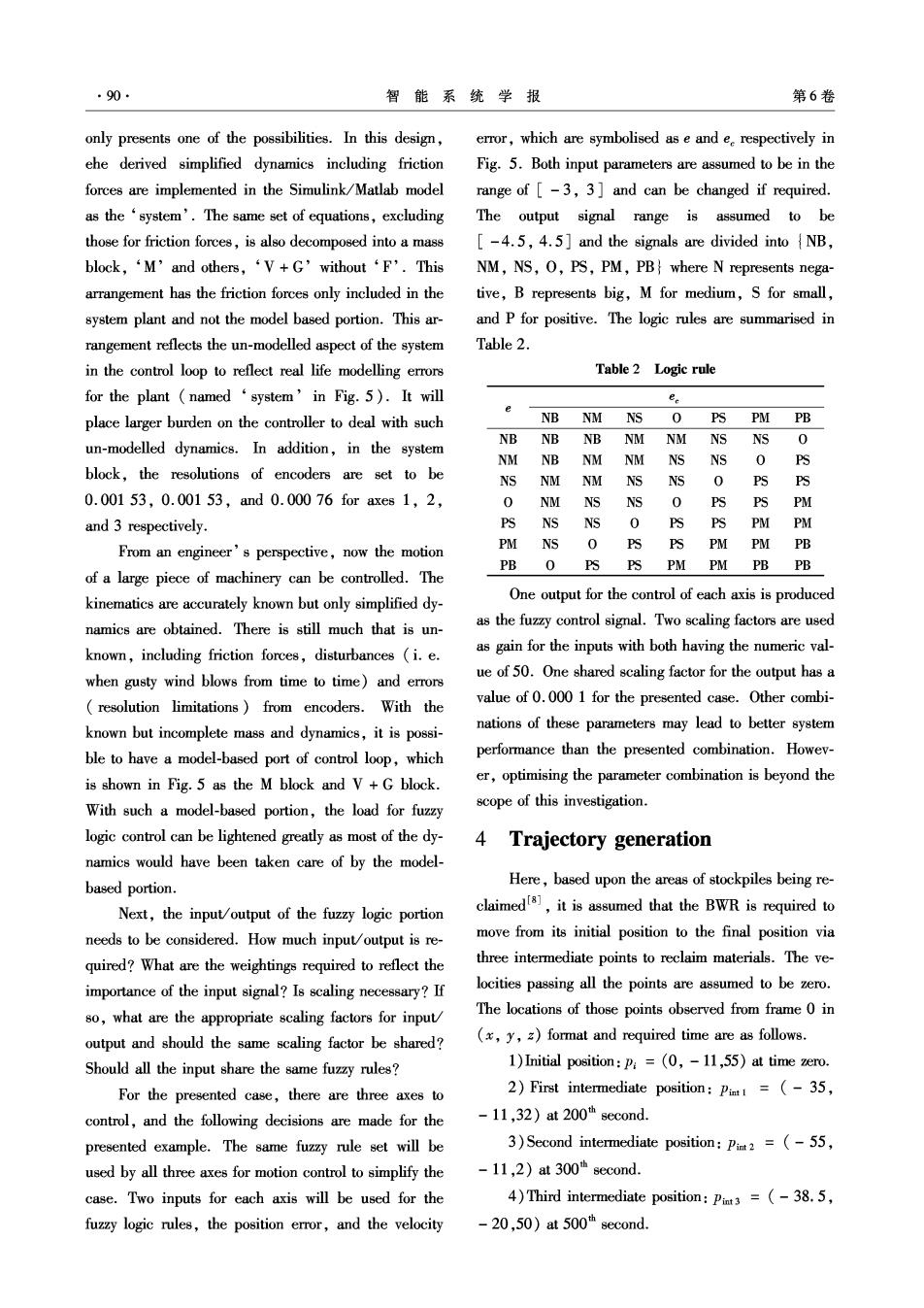
90 智能系统学报 第6卷 only presents one of the possibilities.In this design, error,which are symbolised as e and e respectively in ehe derived simplified dynamics including friction Fig.5.Both input parameters are assumed to be in the forces are implemented in the Simulink/Matlab model range of [-3,3]and can be changed if required. as the 'system'.The same set of equations,excluding The output signal range is assumed to be those for friction forces,is also decomposed into a mass [-4.5,4.5]and the signals are divided into NB, block,‘M'and others,‘V+G'without‘F'.This NM,NS,O,PS,PM,PB where N represents nega- arrangement has the friction forces only included in the tive,B represents big,M for medium,S for small, system plant and not the model based portion.This ar- and P for positive.The logic rules are summarised in rangement reflects the un-modelled aspect of the system Table 2. in the control loop to reflect real life modelling errors Table 2 Logic rule for the plant(named‘system'in Fig.5).It will ee place larger burden on the controller to deal with such NB NM NS 0 PS PM PB NB un-modelled dynamics.In addition,in the system NB NB NM NM NSNS 0 NM NB nm NM NSNS 0 PS block,the resolutions of encoders are set to be NS NM NM NS NS 0 PS PS 0.00153,0.00153,and0.00076 for axes1,2, 0 NM NS NS 0 PS PS PM and 3 respectively. PS NS NS 0 PS PS PM PM From an engineer's perspective,now the motion PM NS 0 PS PS PM PM PB PB O PSPS PM PM PB PB of a large piece of machinery can be controlled.The kinematics are accurately known but only simplified dy- One output for the control of each axis is produced namics are obtained.There is still much that is un- as the fuzzy control signal.Two scaling factors are used known,including friction forces,disturbances (i.e. as gain for the inputs with both having the numeric val- when gusty wind blows from time to time)and errors ue of 50.One shared scaling factor for the output has a resolution limitations)from encoders.With the value of 0.000 1 for the presented case.Other combi- known but incomplete mass and dynamics,it is possi- nations of these parameters may lead to better system ble to have a model-based port of control loop,which performance than the presented combination.Howev- is shown in Fig.5 as the M block and V+G block. er,optimising the parameter combination is beyond the With such a model-based portion,the load for fuzzy scope of this investigation. logic control can be lightened greatly as most of the dy- 4 Trajectory generation namics would have been taken care of by the model- based portion. Here,based upon the areas of stockpiles being re- Next,the input/output of the fuzzy logic portion claimeds,it is assumed that the BWR is required to needs to be considered.How much input/output is re- move from its initial position to the final position via quired?What are the weightings required to reflect the three intermediate points to reclaim materials.The ve- importance of the input signal?Is scaling necessary?If locities passing all the points are assumed to be zero. so,what are the appropriate scaling factors for input The locations of those points observed from frame 0 in output and should the same scaling factor be shared? (x,y,z)format and required time are as follows. Should all the input share the same fuzzy rules? 1)Initial position:P=(0,-11,55)at time zero. For the presented case,there are three axes to 2)First intermediate position:Pit=(-35, control,and the following decisions are made for the -11,32)at200"second. presented example.The same fuzzy rule set will be 3)Second intermediate position:Pimt2 =(-55, used by all three axes for motion control to simplify the -11,2)at 300h second. case.Two inputs for each axis will be used for the 4)Third intermediate position:Pit3=(-38.5, fuzzy logic rules,the position error,and the velocity -20,50)a500"second
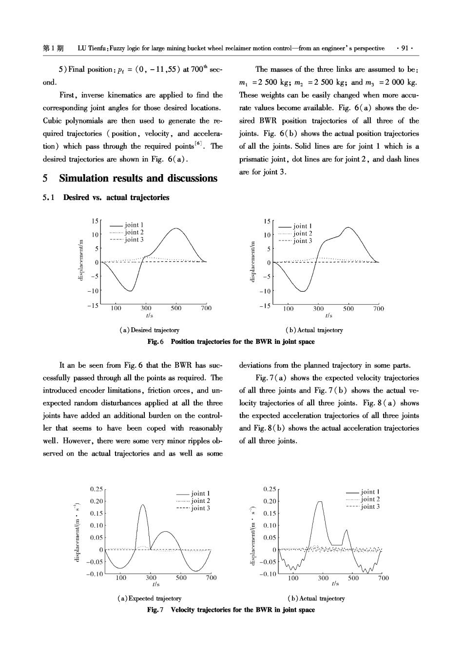
1LU Tienfu:Fuzzy logic for large mining bucket wheel reclaimer motion control-from an engineer's perspective 91. 5)Final position:Pr=(0,-11,55)at 700%h sec- The masses of the three links are assumed to be: ond. m1=2500kg;m2=2500kg;andm3=2000kg. First,inverse kinematics are applied to find the These weights can be easily changed when more accu- corresponding joint angles for those desired locations. rate values become available.Fig.6(a)shows the de- Cubic polynomials are then used to generate the re- sired BWR position trajectories of all three of the quired trajectories (position,velocity,and accelera- joints.Fig.6(b)shows the actual position trajectories tion)which pass through the required points.The of all the joints.Solid lines are for joint 1 which is a desired trajectories are shown in Fig.6(a). prismatic joint,dot lines are for joint 2,and dash lines 5 Simulation results and discussions are for joint 3. 5.1 Desired vs.actual trajectories 15 -joint 1 15 joint I 10 …j0int2 10 .…joint2 --…joint3 --=-…joint3 5 -5 10 -10 15 100 300500 700 -15 100 300500700 tis tis (a)Desired trajectory (b)Actual trajectory Fig.6 Position trajectories for the BWR in joint space It an be seen from Fig.6 that the BWR has suc- deviations from the planned trajectory in some parts cessfully passed through all the points as required.The Fig.7(a)shows the expected velocity trajectories introduced encoder limitations,friction orces,and un- of all three joints and Fig.7(b)shows the actual ve- expected random disturbances applied at all the three locity trajectories of all three joints.Fig.8(a)shows joints have added an additional burden on the control- the expected acceleration trajectories of all three joints ler that seems to have been coped with reasonably and Fig.8(b)shows the actual acceleration trajectories well.However,there were some very minor ripples ob- of all three joints. served on the actual trajectories and as well as some 0.25 -joint 1 0.25 joint I 0.20 …j0int2 0.20 …joint2 ---…joint3 ---…joint3 0.15 0.15 0.10 0.10 0.05 0.05 0 -0.05 -0.05 M 0.10 100 300 500 700 -0.10 100 300 500 700 de (a)Expected trajectory (b)Actual trajectory Fig.7 Velocity trajectories for the BWR in joint space

92 智能系统学报 第6卷 The actual velocity trajectory profiles shown in Fig.7 (b)seem to be related to the larger velocity switches as (b)basically follow the profiles of the desired trajectories can be seen from Fig.7(b).Similar effects can also be shown in Fig.7(a).However,the ripples shown in Fig.7 observed in Fig.8 for the acceleration. ×10 ×10 joint I joint 2 joint 1 ........jioint 2 Joint 3 ----joint 3 2 0 -2 -3 100 300 500 700 100 300 500 700 tis (a)Expected trajectory (b)Actual trajectory Fig.8 Acceleration trajectories for the BWR in joint space 5.2 Trajectory errors Further investigation reveals that the velocity ×10 switching behaviours in Fig.7 are caused mainly by the fuzzy logic control loop which has been applied.This is evident from Fig.9 which shows the output from the fuzzy logic control signals that is used to control the motion of the system.Even though the averaged values come very close to the desired acceleration trajectories, =4 the control signals produce something like digital swit- -5 100 300 500 700 ches for on (positive maximum or negative maximum) t/s or off (zero). Fig.9 Output control signals from fuzzy logic joint I 0.15 Joint 1 ×10 joint 1 …joint2 0.10 joint 2 …joint2 joint 3 -…joint3 0.05 4 Joint 3 -0.05 -0.10 -4 写-015 -6 -0.20 -8 100300。 500 700 100 300 500 700 100300 500700 1/s s Fig.10 Position,velocity,and acceleration errors(from left to right) Fig.10 shows the position,velocity,and acceler- rameters discussed in Section IlI related to a fuzzy logic ation errors.The maximum errors are -4 m at a time control loop and controller design are re-visited in the of around 340th of a second,-0.17ms,and following section in order to improve system perform- 0.0075mreepectively.Obviously,axis 1 has ance.It is understood that by changing the parameters the most position errors deviating away from the desired and arrangement,differing system performances can be trajectory which can be further improved as seen from expected for better or worse. the figure. 5.3 Controller design modification and improved From an engineer's perspective,if the most im- results portant position trajectory-following target has been From Fig.10,it is obvious that axis 1 has much met,it might not be necessary to further investigate larger errors in position,velocity,and acceleration and improve the performance.Nevertheless,the pa-
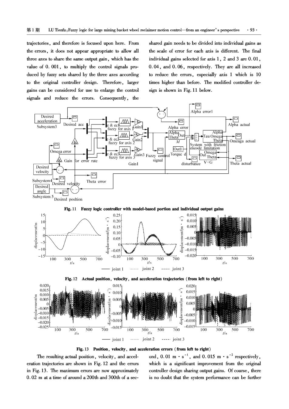
1 LU Tienfu:Fuzzy logic for large mining bucket wheel reclaimer motion control-from an engineer's perspective ·93 trajectories,and therefore is focused upon here.From shared gain needs to be divided into individual gains as the errors,it does not appear appropriate to allow all the scale of error for each axis is different.The final three axes to share the same output gain,which has the individual gains selected for axis 1,2 and 3 are 0.01, value of 0.001,to multiply the control signals pro- 0.04,and 0.06,respectively.They are all increased duced by fuzzy sets shared by the three axes according to reduce the errors,especially axis 1 which is 10 to the original controller design.Therefore,larger times higher than before.The modified controller de- gains can be considered for use to enlarge the control sign is shown in Fig.11 below. signals and reduce the errors.Consequently,the Alpha errorl Desired acceleration +回 回 R Subsystem3 Desired acc Alpha actual for axi ain Alpha error Alpha Tau Omega 回 K fuzzy for axis M Theta Omeaga actual System with friction Out1 encode limitation Omega error fuzzy for axis 3Gain3 Fuzzy control Torque d Omega Theta. Gain or error rate signal 回 Gainl disturbance V+G Theta actual Desired velocity 回 Subsystem Desired velocity Theta error Desired angle 同 Subsystem 5 Desired posltion Fig.11 Fuzzy logic controller with model-based portion and individual output gains 15 0.25 0.015r 0.20 0.010 5 0.15 0.005 0.10 0.05 -0.005 A -0.01C -10 -0.05 -0.015 -15 -0.10 -0.020 100 300 500 700 100 300 500 700 100 300 500 700 tis tls tis joint I joint 2 ---…joint3 Fg.12 Actual position,velocity,and acceleration trajectories from left to right) 0.020 0.015 0.020 0.059 0.010 0.010 0.015 0.005 0.010 J 0.005 s-0005 0 -0.010 -0.05 0.005 克-0.015 -0.020 元-0.010 -0.010 0.025 0.015 100 300 500 700-0.0154 100 300 500700 100 300 500 700 -joint I …joint2 ----.joint 3 Fig.13 Position,velocity,and acceleration errors (from left to right) The resulting actual position,velocity,and accel-ond,0.01 m.s-,and 0.015 m.s-2respectively, eration trajectories are shown in Fig.12 and the errors which is a significant improvement from the original in Fig.13.The maximum errors are now approximately controller design sharing output gains.Of course,there 0.02 m at a time of around a 200th and 300th of a sec- is no doubt that the system performance can be further
94 智能系统学报 第6卷 improved,especially in the velocity and acceleration al Conference on Systems,Man,and Cybernetics.Orlando, trajectories by changing factors such as the fuzzy rules, USA,1997:2883-2887. the gain values,and so on as mentioned in Section III [3 ]CHOI C,LEE K,SHIN K,et al.Automatic landing meth- covering controller design.If the main target is od of a reclaimer on the stockpile[J].IEEE Transactions on Systems,Man,and Cybernetics-Part C:Applications and changed from following the position trajectories to areas Reviews,1999,29(1):308-314. such as velocity trajectories,the fuzzy rules,and the [4]HONG K S,CHOI C.Task-oriented approaches to the in- gains,other aspects of the controller will need to be verse kinematics problem for a reclaimer excavating and changed to produce satisfactory results.Nevertheless, transporting raw material[J].Advanced Robotics,2000, this exercise demonstrates the presented model and 14(3):185-204. simulation environment is capable of reflecting a real [5 LU Tienfu.Bucket wheel reclaimer modelling as a robotic BWR and being used to develop appropriate control arm[C]//IEEE Intermational Conference on Robotics and strategies for the physical control of a BWR. Biomimetics.Guilin,China,2009:263-268. [6]LU Tienfu.Preparation for tumning a bucket wheel reclaimer 6 Conclusion into a robotic arm C]//IEEE International Conference on Robotics and Biomimetics.Bangkok,Thailand,2008: This paper presents the implementation of fuzzy 1710-1715. logic for the motion control of a large BWR to follow [7]LU Tienfu,LIN G C.Intelligent systems techniques and given trajectories in a simulated environment.The con- their application in manufacturing systems[M]//LEONDES tent covers the modelling of a typical BWR using Mat- C T.Expert systems:the technology of knowledge manage- lab/Simulink and includes not only the kinematics and ment and decision making for the 21st century.San Diego, simplified dynamics but also the friction forces from its USA:Academic Press,2002:381-410. joints,limitations of its encoder resolutions,and unex- [8]LU Tienfu,MYO M T R.Optimization of reclaiming voxels pected random disturbances to cover the un-modelled for quality grade target with reclaimer minimum movement [C]//The Eleventh Interational Conference on Control, dynamics.Additionally,a hybrid controller,which Automation,Robotics and Vision(ICARCV 2010).Singa- consists of a fuzzy logic controller on top of a model pore,2010:1350-1410. based example,is developed and implemented.The About the author: paper provides engineers with an example of applying LU Tienfu received his Bachelor of fuzzy logic together with a model based approach to Science and Master of Science in Mechan- properly control the motion of a large BWR to follow ical Engineering from National Cheng defined trajectories as well as possible ways to further Kung University,Taiwan in 1988 and improve the controller performance. 1990 respectively.He received his PhD in Manufacturing and Mechanical Engineer- Acnowledgment ing from the University of South Australia in 1997.He was a postdoctoral researcher at the University of The authors would like to thank Australian Re- South Australia between 1997 and 2000.Since 2001,he has search Council and Industry Partner,Matrix Group Lty been with the School of Mechanical Engineering,University of Ltd.for the financial and in-kind support through the Adelaide and is currently a senior lecturer.He is the leader of ARC Linkage LP0989780 grant titled "The study and the robotics research lab at the University of Adelaide and his development of a 3-D real-time stockpile management current research interests include intelligent mobile robotics system"and the support in part from Institute for Min- (modelling,trajectory planning,localisation,and navigation), eral and Energy Resources,University of Adelaide underwater robotics modelling,localisation,and navigation), 2009-2010,as well as Faculty of Engineering,Com- insect robotics chemical plume source localisation),mecha- puter and Mathematical Sciences strategic research fun- tronic technologies in mining,and micro-motion robotic systems pzt actuator modelling and control,and micro-motion stages). ding,2010. He is a member of the IEEE and currently an associate Editor of References: the Australian Journal of Mechanical Engineering (AJME),En- gineers Australia,and a member of the International Journal of [1]LU Tienfu,XU Shihong.SPSim:a stockpile simulator for Intelligent Mechatronics and Robotics (IJIMR)Editorial Board. analyzing material quality distribution in mining[C]//Inter- He has so far published one Australian provisional patent,three national Conference on Mechatronics and Automation (IC- book chapters,26 journal papers and more than 80 conference MA2010).Xi'an,China,2010:299-304. papers. [2]CHOI C,LEE K,SHIN K,et al.Inverse kinematics of a reclaimer:redundancy and solution[C]//IEEE Internation-