正在加载图片...
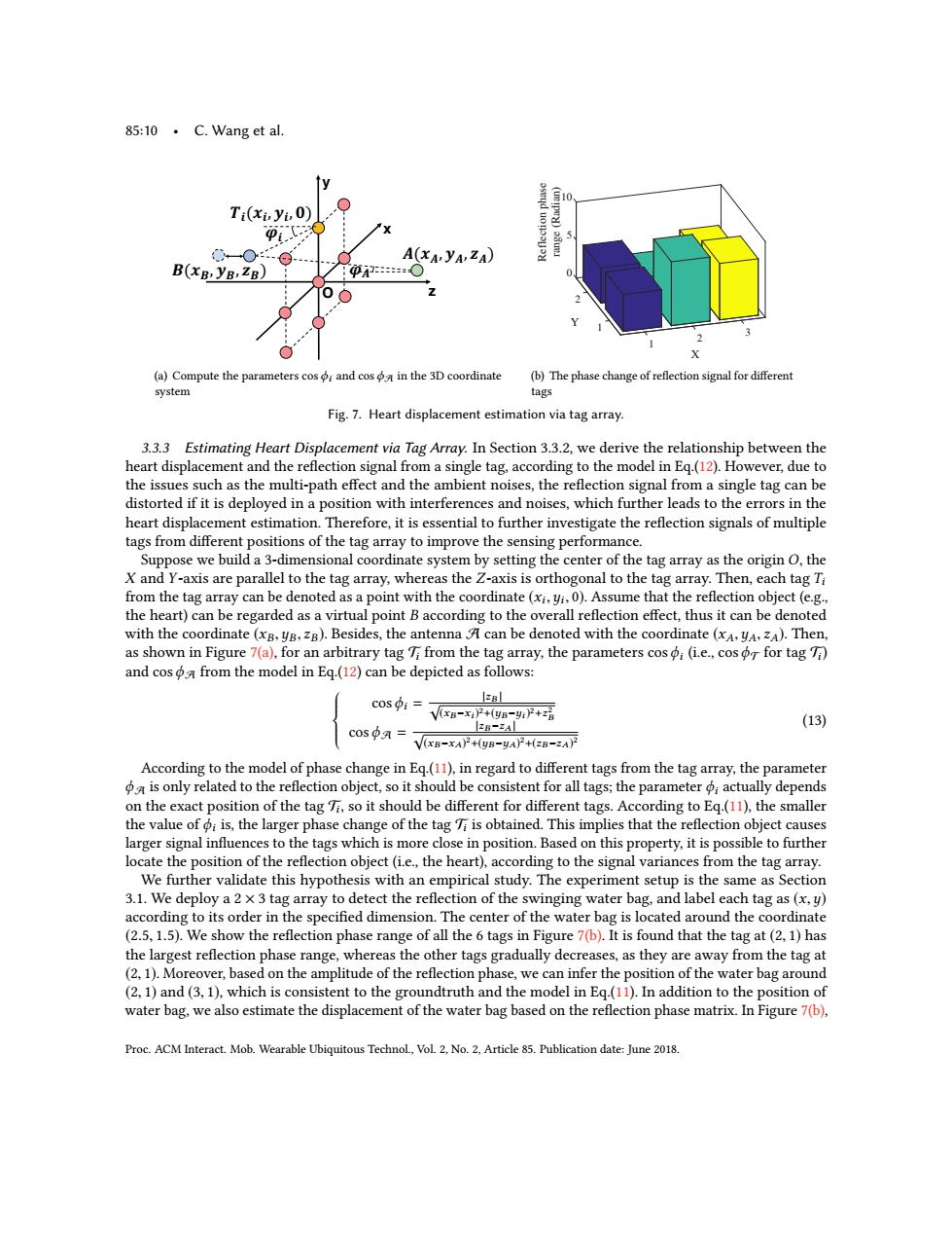
85:10·C.Wang et al.. fy Ti(xiyiO) Pit X 0-O-@ A(xA,yA,ZA) B(xB,yB,ZB) 项○ 中 (a)Compute the parameters cos;and cos in the 3D coordinate (b)The phase change of reflection signal for different system tags Fig.7.Heart displacement estimation via tag array. 3.3.3 Estimating Heart Displacement via Tag Array.In Section 3.3.2,we derive the relationship between the heart displacement and the reflection signal from a single tag,according to the model in Eq.(12).However,due to the issues such as the multi-path effect and the ambient noises,the reflection signal from a single tag can be distorted if it is deployed in a position with interferences and noises,which further leads to the errors in the heart displacement estimation.Therefore,it is essential to further investigate the reflection signals of multiple tags from different positions of the tag array to improve the sensing performance. Suppose we build a 3-dimensional coordinate system by setting the center of the tag array as the origin O,the X and Y-axis are parallel to the tag array,whereas the Z-axis is orthogonal to the tag array.Then,each tag Ti from the tag array can be denoted as a point with the coordinate(xi,yi.0).Assume that the reflection object(e.g., the heart)can be regarded as a virtual point B according to the overall reflection effect,thus it can be denoted with the coordinate(xB,yB,zg).Besides,the antenna A can be denoted with the coordinate (xA,yA,ZA).Then, as shown in Figure 7(a),for an arbitrary tag 7i from the tag array,the parameters cos ;(i.e.,cos o for tag 7i) and cosa from the model in Eq.(12)can be depicted as follows: C0s9:= VxB-xP+(yB-1P+z话 (13) C0sφA= V(xB-xA)2+(yB-yA)+(zB-zA)2 According to the model of phase change in Eq.(11),in regard to different tags from the tag array,the parameter a is only related to the reflection object,so it should be consistent for all tags;the parameter actually depends on the exact position of the tag Ti,so it should be different for different tags.According to Eq.(11),the smaller the value of i is,the larger phase change of the tag Ti is obtained.This implies that the reflection object causes larger signal influences to the tags which is more close in position.Based on this property,it is possible to further locate the position of the reflection object(i.e.,the heart),according to the signal variances from the tag array. We further validate this hypothesis with an empirical study.The experiment setup is the same as Section 3.1.We deploy a 2 x 3 tag array to detect the reflection of the swinging water bag,and label each tag as(x,y) according to its order in the specified dimension.The center of the water bag is located around the coordinate (2.5,1.5).We show the reflection phase range of all the 6 tags in Figure 7(b).It is found that the tag at(2,1)has the largest reflection phase range,whereas the other tags gradually decreases,as they are away from the tag at (2,1).Moreover,based on the amplitude of the reflection phase,we can infer the position of the water bag around (2,1)and (3,1),which is consistent to the groundtruth and the model in Eq.(11).In addition to the position of water bag,we also estimate the displacement of the water bag based on the reflection phase matrix.In Figure 7(b), Proc.ACM Interact.Mob.Wearable Ubiquitous Technol,Vol.2,No.2,Article 85.Publication date:June 2018.85:10 • C. Wang et al. x z y !"#$" % &" % '( )#$)% &)% *)( +" ,#$,% &,% *,( +) O (a) Compute the parameters cos ϕi and cos ϕA in the 3D coordinate system 3 2 X 1 1 2 Y 10 5 0 Reflection phase range (Radian) (b) The phase change of reflection signal for different tags Fig. 7. Heart displacement estimation via tag array. 3.3.3 Estimating Heart Displacement via Tag Array. In Section 3.3.2, we derive the relationship between the heart displacement and the reflection signal from a single tag, according to the model in Eq.(12). However, due to the issues such as the multi-path effect and the ambient noises, the reflection signal from a single tag can be distorted if it is deployed in a position with interferences and noises, which further leads to the errors in the heart displacement estimation. Therefore, it is essential to further investigate the reflection signals of multiple tags from different positions of the tag array to improve the sensing performance. Suppose we build a 3-dimensional coordinate system by setting the center of the tag array as the origin O, the X and Y-axis are parallel to the tag array, whereas the Z-axis is orthogonal to the tag array. Then, each tag Ti from the tag array can be denoted as a point with the coordinate (xi ,yi , 0). Assume that the reflection object (e.g., the heart) can be regarded as a virtual point B according to the overall reflection effect, thus it can be denoted with the coordinate (xB,yB, zB). Besides, the antenna A can be denoted with the coordinate (xA,yA, zA). Then, as shown in Figure 7(a), for an arbitrary tag Ti from the tag array, the parameters cosϕi (i.e., cosϕT for tag Ti ) and cosϕA from the model in Eq.(12) can be depicted as follows: cosϕi = |zB | √ (xB −xi ) 2+(yB −yi ) 2+z 2 B cosϕA = |zB −zA | √ (xB −xA) 2+(yB −yA) 2+(zB −zA) 2 (13) According to the model of phase change in Eq.(11), in regard to different tags from the tag array, the parameter ϕA is only related to the reflection object, so it should be consistent for all tags; the parameter ϕi actually depends on the exact position of the tag Ti , so it should be different for different tags. According to Eq.(11), the smaller the value of ϕi is, the larger phase change of the tag Ti is obtained. This implies that the reflection object causes larger signal influences to the tags which is more close in position. Based on this property, it is possible to further locate the position of the reflection object (i.e., the heart), according to the signal variances from the tag array. We further validate this hypothesis with an empirical study. The experiment setup is the same as Section 3.1. We deploy a 2 × 3 tag array to detect the reflection of the swinging water bag, and label each tag as (x,y) according to its order in the specified dimension. The center of the water bag is located around the coordinate (2.5, 1.5). We show the reflection phase range of all the 6 tags in Figure 7(b). It is found that the tag at (2, 1) has the largest reflection phase range, whereas the other tags gradually decreases, as they are away from the tag at (2, 1). Moreover, based on the amplitude of the reflection phase, we can infer the position of the water bag around (2, 1) and (3, 1), which is consistent to the groundtruth and the model in Eq.(11). In addition to the position of water bag, we also estimate the displacement of the water bag based on the reflection phase matrix. In Figure 7(b), Proc. ACM Interact. Mob. Wearable Ubiquitous Technol., Vol. 2, No. 2, Article 85. Publication date: June 2018