正在加载图片...
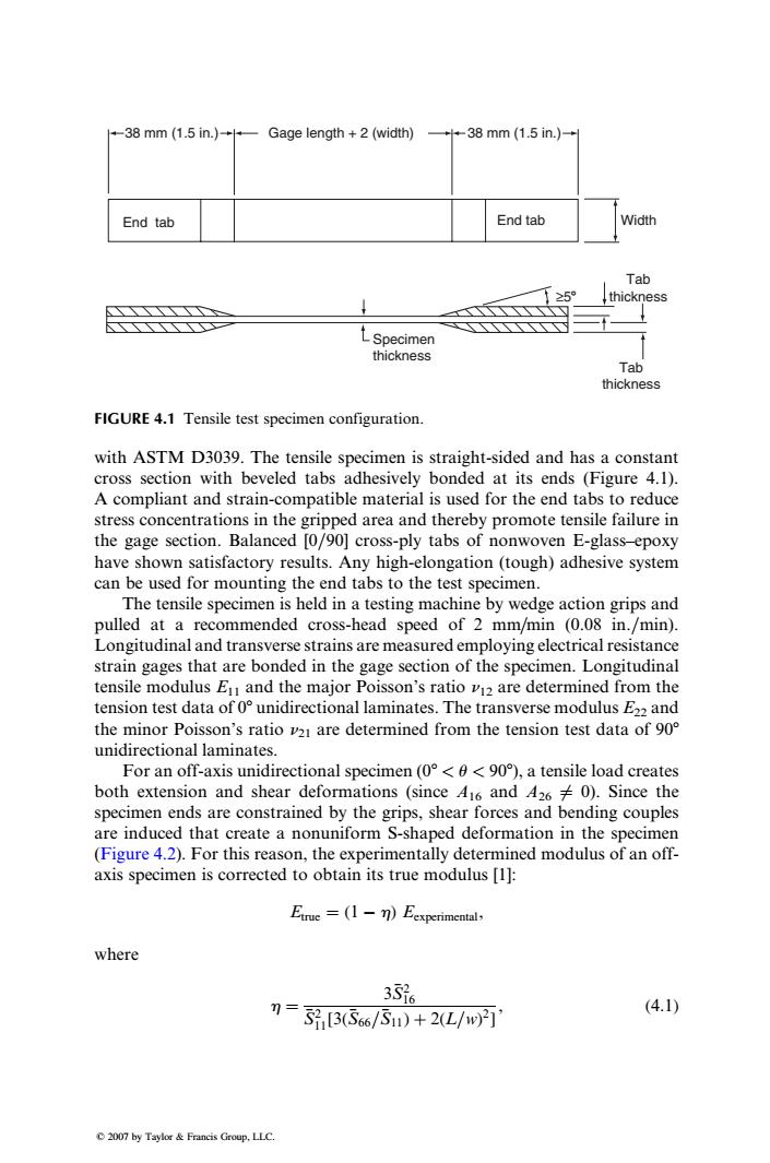
-38 mm (1.5 in.)Gage length +2(width) +中-38mm(15in.)+ End tab End tab Width Tab 25 thickness LSpecimen thickness Tab thickness FIGURE 4.1 Tensile test specimen configuration. with ASTM D3039.The tensile specimen is straight-sided and has a constant cross section with beveled tabs adhesively bonded at its ends (Figure 4.1). A compliant and strain-compatible material is used for the end tabs to reduce stress concentrations in the gripped area and thereby promote tensile failure in the gage section.Balanced [0/90]cross-ply tabs of nonwoven E-glass-epoxy have shown satisfactory results.Any high-elongation (tough)adhesive system can be used for mounting the end tabs to the test specimen. The tensile specimen is held in a testing machine by wedge action grips and pulled at a recommended cross-head speed of 2 mm/min (0.08 in./min). Longitudinal and transverse strains are measured employing electrical resistance strain gages that are bonded in the gage section of the specimen.Longitudinal tensile modulus Eu and the major Poisson's ratio v12 are determined from the tension test data of o unidirectional laminates.The transverse modulus E22 and the minor Poisson's ratio vz are determined from the tension test data of 90 unidirectional laminates. For an off-axis unidirectional specimen (0<0<90),a tensile load creates both extension and shear deformations (since 416 and 4260).Since the specimen ends are constrained by the grips,shear forces and bending couples are induced that create a nonuniform S-shaped deformation in the specimen (Figure 4.2).For this reason,the experimentally determined modulus of an off- axis specimen is corrected to obtain its true modulus [1]: Etrue =(1-m)Eexperimental, where 356 7=3,356/5)+2L/wT' (4.1) 2007 by Taylor Francis Group,LLC.with ASTM D3039. The tensile specimen is straight-sided and has a constant cross section with beveled tabs adhesively bonded at its ends (Figure 4.1). A compliant and strain-compatible material is used for the end tabs to reduce stress concentrations in the gripped area and thereby promote tensile failure in the gage section. Balanced [0=90] cross-ply tabs of nonwoven E-glass–epoxy have shown satisfactory results. Any high-elongation (tough) adhesive system can be used for mounting the end tabs to the test specimen. The tensile specimen is held in a testing machine by wedge action grips and pulled at a recommended cross-head speed of 2 mm=min (0.08 in.=min). Longitudinal and transverse strains are measured employing electrical resistance strain gages that are bonded in the gage section of the specimen. Longitudinal tensile modulus E11 and the major Poisson’s ratio n12 are determined from the tension test data of 08 unidirectional laminates. The transverse modulus E22 and the minor Poisson’s ratio n21 are determined from the tension test data of 908 unidirectional laminates. For an off-axis unidirectional specimen (08 < u < 908), a tensile load creates both extension and shear deformations (since A16 and A26 6¼ 0). Since the specimen ends are constrained by the grips, shear forces and bending couples are induced that create a nonuniform S-shaped deformation in the specimen (Figure 4.2). For this reason, the experimentally determined modulus of an offaxis specimen is corrected to obtain its true modulus [1]: Etrue ¼ (1 h) Eexperimental, where h ¼ 3S2 16 S2 11[3(S66=S11) þ 2(L=w) 2 ] , (4:1) ≥58 Specimen thickness Tab thickness Tab thickness End tab Width 38 mm (1.5 in.) Gage length + 2 (width) 38 mm (1.5 in.) End tab FIGURE 4.1 Tensile test specimen configuration. 2007 by Taylor & Francis Group, LLC.�