正在加载图片...
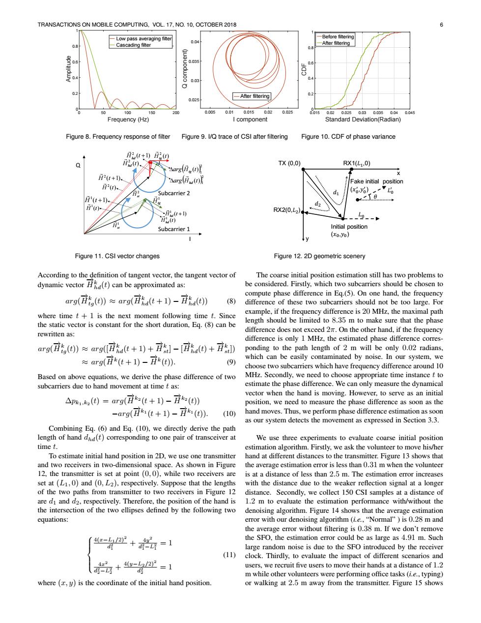
TRANSACTIONS ON MOBILE COMPUTING,VOL.17,NO.10,OCTOBER 2018 -Low pass averaging filter 一Before filtering 0.04 0.8 -Cascading filter e -After filtering 0.8 .035 0.03 0.4 02 0.025 一After filtering 50 100 150 200 0.005 0.010.0150.02 0.025 00150.020.0250.030.0350.040.045 Frequency (Hz) I component Standard Deviation(Radian) Figure 8.Frequency response of filter Figure 9.l/Q trace of CSI after filtering Figure 10.CDF of phase variance t+)g H2(t). TX(0.0) arg(日.() RX1(L1.0) 月2(1+1). "Aarg(H(t Fake initial position H2(t)- Subcarrier 2 (x0%) i'(t+). H(小 +) RX2(0,L2) HO -9-- Subcarrier 1 Initial position (xo.yo) V Figure 11.CSI vector changes Figure 12.2D geometric scenery According to the definition of tangent vector,the tangent vector of The coarse initial position estimation still has two problems to dynamic vector (t)can be approximated as: be considered.Firstly,which two subcarriers should be chosen to compute phase difference in Eq.(5).On one hand,the frequency arg((t))arg(Ha(t+1)-a(t)) (8) difference of these two subcarriers should not be too large.For where time t+1 is the next moment following time t.Since example,if the frequency difference is 20 MHz,the maximal path the static vector is constant for the short duration,Eq.(8)can be length should be limited to 8.35 m to make sure that the phase difference does not exceed 2.On the other hand,if the frequency rewritten as: difference is only 1 MHz,the estimated phase difference corres- arg(H(t))arg([Ha(t+1)+-[d(t)+) ponding to the path length of 2 m will be only 0.02 radians, ≈arg((t+1)-i() which can be easily contaminated by noise.In our system,we (9) choose two subcarriers which have frequency difference around 10 Based on above equations,we derive the phase difference of two MHz.Secondly,we need to choose appropriate time instance t to subcarriers due to hand movement at time t as: estimate the phase difference.We can only measure the dynamical △p1(=arg(i(t+1)-7()】 vector when the hand is moving.However,to serve as an initial position,we need to measure the phase difference as soon as the -arg(i1(t+1)-i() (10) hand moves.Thus,we perform phase difference estimation as soon as our system detects the movement as expressed in Section 3.3. Combining Eq.(6)and Eq.(10),we directly derive the path length of hand dhd(t)corresponding to one pair of transceiver at We use three experiments to evaluate coarse initial position time t. estimation algorithm.Firstly,we ask the volunteer to move his/her To estimate initial hand position in 2D,we use one transmitter hand at different distances to the transmitter.Figure 13 shows that and two receivers in two-dimensional space.As shown in Figure the average estimation error is less than 0.31 m when the volunteer 12,the transmitter is set at point(0,0),while two receivers are is at a distance of less than 2.5 m.The estimation error increases set at(L1,0)and(0,L2),respectively.Suppose that the lengths with the distance due to the weaker reflection signal at a longer of the two paths from transmitter to two receivers in Figure 12 distance.Secondly,we collect 150 CSI samples at a distance of are di and d2,respectively.Therefore,the position of the hand is 1.2 m to evaluate the estimation performance with/without the the intersection of the two ellipses defined by the following two denoising algorithm.Figure 14 shows that the average estimation equations: error with our denoising algorithm (ie.,"Normal")is 0.28 m and the average error without filtering is 0.38 m.If we don't remove -心+=1 the SFO,the estimation error could be as large as 4.91 m.Such d large random noise is due to the SFO introduced by the receiver (11) clock.Thirdly,to evaluate the impact of different scenarios and (+w-名2-1 4x2 users,we recruit five users to move their hands at a distance of 1.2 d m while other volunteers were performing office tasks(i.e.,typing) where (y)is the coordinate of the initial hand position. or walking at 2.5 m away from the transmitter.Figure 15 showsTRANSACTIONS ON MOBILE COMPUTING, VOL. 17, NO. 10, OCTOBER 2018 6 0 50 100 150 200 Frequency (Hz) 0 0.2 0.4 0.6 0.8 1 Amplitude Low pass averaging filter Cascading filter Figure 8. Frequency response of filter 0.005 0.01 0.015 0.02 0.025 I component 0.025 0.03 0.035 0.04 Q component) After filtering Figure 9. I/Q trace of CSI after filtering 0.015 0.02 0.025 0.03 0.035 0.04 0.045 Standard Deviation(Radian) 0 0.2 0.4 0.6 0.8 1 CDF Before filtering After filtering Figure 10. CDF of phase variance Subcarrier 1 Subcarrier 2 Q I ( 1) 1 H t ( ) 1 H t 1 Htg ( ) 2 H t tg ( 1) 2 H t ( ) 2 H t ( ) 1 H t hd ( ) 2 H t hd 2 1 arg H (t) tg 2 1 arg H (t) hd 1 Hst 2 Hst ( 1) 2 Hhd t ( 1) 1 Hhd t Figure 11. CSI vector changes y TX (0,0) RX2(0,�") RX1(�#,0) Initial position (�%,�%) x Fake initial position (�% ' ,�% ' ) �% �% ' � �# �" Figure 12. 2D geometric scenery According to the definition of tangent vector, the tangent vector of dynamic vector −→Hk hd(t) can be approximated as: arg( −→Hk tg(t)) ≈ arg( −→Hk hd(t + 1) − −→Hk hd(t)) (8) where time t + 1 is the next moment following time t. Since the static vector is constant for the short duration, Eq. (8) can be rewritten as: arg( −→Hk tg(t)) ≈ arg([−→Hk hd(t + 1) + −→Hk st] − [ −→Hk hd(t) + −→Hk st]) ≈ arg( −→Hk (t + 1) − −→Hk (t)). (9) Based on above equations, we derive the phase difference of two subcarriers due to hand movement at time t as: ∆pk1,k2 (t) = arg( −→Hk2 (t + 1) − −→Hk2 (t)) −arg( −→Hk1 (t + 1) − −→Hk1 (t)). (10) Combining Eq. (6) and Eq. (10), we directly derive the path length of hand dhd(t) corresponding to one pair of transceiver at time t. To estimate initial hand position in 2D, we use one transmitter and two receivers in two-dimensional space. As shown in Figure 12, the transmitter is set at point (0, 0), while two receivers are set at (L1, 0) and (0, L2), respectively. Suppose that the lengths of the two paths from transmitter to two receivers in Figure 12 are d1 and d2, respectively. Therefore, the position of the hand is the intersection of the two ellipses defined by the following two equations: 4(x−L1/2)2 d 2 1 + 4y 2 d 2 1−L2 1 = 1 4x 2 d 2 2−L2 2 + 4(y−L2/2)2 d 2 2 = 1 (11) where (x, y) is the coordinate of the initial hand position. The coarse initial position estimation still has two problems to be considered. Firstly, which two subcarriers should be chosen to compute phase difference in Eq.(5). On one hand, the frequency difference of these two subcarriers should not be too large. For example, if the frequency difference is 20 MHz, the maximal path length should be limited to 8.35 m to make sure that the phase difference does not exceed 2π. On the other hand, if the frequency difference is only 1 MHz, the estimated phase difference corresponding to the path length of 2 m will be only 0.02 radians, which can be easily contaminated by noise. In our system, we choose two subcarriers which have frequency difference around 10 MHz. Secondly, we need to choose appropriate time instance t to estimate the phase difference. We can only measure the dynamical vector when the hand is moving. However, to serve as an initial position, we need to measure the phase difference as soon as the hand moves. Thus, we perform phase difference estimation as soon as our system detects the movement as expressed in Section 3.3. We use three experiments to evaluate coarse initial position estimation algorithm. Firstly, we ask the volunteer to move his/her hand at different distances to the transmitter. Figure 13 shows that the average estimation error is less than 0.31 m when the volunteer is at a distance of less than 2.5 m. The estimation error increases with the distance due to the weaker reflection signal at a longer distance. Secondly, we collect 150 CSI samples at a distance of 1.2 m to evaluate the estimation performance with/without the denoising algorithm. Figure 14 shows that the average estimation error with our denoising algorithm (i.e., “Normal” ) is 0.28 m and the average error without filtering is 0.38 m. If we don’t remove the SFO, the estimation error could be as large as 4.91 m. Such large random noise is due to the SFO introduced by the receiver clock. Thirdly, to evaluate the impact of different scenarios and users, we recruit five users to move their hands at a distance of 1.2 m while other volunteers were performing office tasks (i.e., typing) or walking at 2.5 m away from the transmitter. Figure 15 shows