正在加载图片...

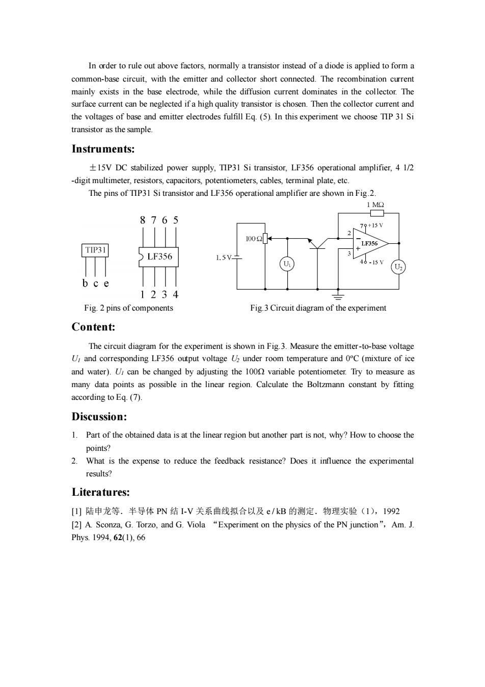
In order to rule out above factors,normally a transistor instead of a diode is applied to form a common-base circuit,with the emitter and collector short connected.The recombination current mainly exists in the base electrode,while the diffusion current dominates in the collector.The surface current can be neglected if a high quality transistor is chosen.Then the collector current and the voltages of base and emitter electrodes fulfill Eq.(5).In this experiment we choose TIP 31 Si transistor as the sample. Instruments: 15V DC stabilized power supply,TIP31 Si transistor,LF356 operational amplifier,4 1/2 -digit multimeter,resistors,capacitors,potentiometers,cables,terminal plate,etc. The pins of TIP31 Si transistor and LF356 operational amplifier are shown in Fig.2. 1 MO 8765 79+15V 1002 LF356 TIP31 LF356 1.5 15V bce 1234 Fig.2 pins of components Fig.3 Circuit diagram of the experiment Content: The circuit diagram for the experiment is shown in Fig.3.Measure the emitter-to-base voltage U and corresponding LF356 output voltage U under room temperature and 0C(mixture of ice and water).U,can be changed by adjusting the 1000 variable potentiometer.Try to measure as many data points as possible in the linear region.Calculate the Boltzmann constant by fitting according to Eq.(7). Discussion: 1.Part of the obtained data is at the linear region but another part is not,why?How to choose the points? 2.What is the expense to reduce the feedback resistance?Does it influence the experimental results? Literatures: [1]陆申龙等.半导体PN结I-V关系曲线拟合以及e/kB的测定.物理实验(1),1992 [2]A.Sconza,G.Torzo,and G.Viola "Experiment on the physics of the PN junction",Am.J. Phys.1994,62(1),66In order to rule out above factors, normally a transistor instead of a diode is applied to form a common-base circuit, with the emitter and collector short connected. The recombination current mainly exists in the base electrode, while the diffusion current dominates in the collector. The surface current can be neglected if a high quality transistor is chosen. Then the collector current and the voltages of base and emitter electrodes fulfill Eq. (5). In this experiment we choose TIP 31 Si transistor as the sample. Instruments: ±15V DC stabilized power supply, TIP31 Si transistor, LF356 operational amplifier, 4 1/2 -digit multimeter, resistors, capacitors, potentiometers, cables, terminal plate, etc. The pins of TIP31 Si transistor and LF356 operational amplifier are shown in Fig.2. Fig. 2 pins of components Fig.3 Circuit diagram of the experiment Content: The circuit diagram for the experiment is shown in Fig.3. Measure the emitter-to-base voltage U1 and corresponding LF356 output voltage U2 under room temperature and 0oC (mixture of ice and water). U1 can be changed by adjusting the 100Ω variable potentiometer. Try to measure as many data points as possible in the linear region. Calculate the Boltzmann constant by fitting according to Eq. (7). Discussion: 1. Part of the obtained data is at the linear region but another part is not, why? How to choose the points? 2. What is the expense to reduce the feedback resistance? Does it influence the experimental results? Literatures: [1] 陆申龙等.半导体 PN 结 I-V 关系曲线拟合以及 e / kB 的测定.物理实验(1),1992 [2] A. Sconza, G. Torzo, and G. Viola “Experiment on the physics of the PN junction”,Am. J. Phys. 1994, 62(1), 66