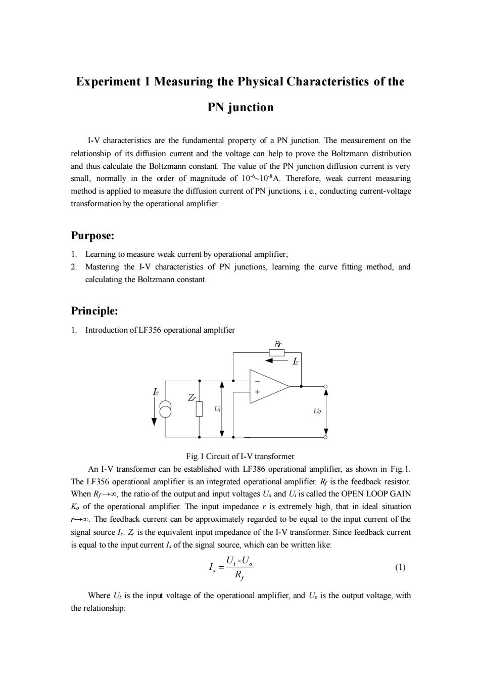
Experiment 1 Measuring the Physical Characteristics of the PN junction I-V characteristics are the fundamental property of a PN junction.The measurement on the relationship of its diffusion current and the voltage can help to prove the Boltzmann distribution and thus calculate the Boltzmann constant.The value of the PN junction diffusion current is very small,normally in the order of magnitude of 106-108A.Therefore,weak current measuring method is applied to measure the diffusion current of PN junctions,i.e.,conducting current-voltage transformation by the operational amplifier. Purpose: 1.Learning to measure weak current by operational amplifier; 2.Mastering the I-V characteristics of PN junctions,learning the curve fitting method,and calculating the Boltzmann constant. Principle: 1.Introduction of LF356 operational amplifier Lo Fig.1 Circuit of I-V transformer An I-V transformer can be established with LF386 operational amplifier,as shown in Fig.1. The LF356 operational amplifier is an integrated operational amplifier.R is the feedback resistor. When Ro,the ratio of the output and input voltages Uo and U is called the OPEN LOOP GAIN Ko of the operational amplifier.The input impedance r is extremely high,that in ideal situation r.The feedback current can be approximately regarded to be equal to the input current of the signal sourceIs.Z is the equivalent input impedance of the I-V transformer.Since feedback current is equal to the input current /s of the signal source,which can be written like: _U,U。 I.=- R (1) Where Ui is the input voltage of the operational amplifier,and U is the output voltage,with the relationship:
Experiment 1 Measuring the Physical Characteristics of the PN junction I-V characteristics are the fundamental property of a PN junction. The measurement on the relationship of its diffusion current and the voltage can help to prove the Boltzmann distribution and thus calculate the Boltzmann constant. The value of the PN junction diffusion current is very small, normally in the order of magnitude of 10-6~10-8A. Therefore, weak current measuring method is applied to measure the diffusion current of PN junctions, i.e., conducting current-voltage transformation by the operational amplifier. Purpose: 1. Learning to measure weak current by operational amplifier; 2. Mastering the I-V characteristics of PN junctions, learning the curve fitting method, and calculating the Boltzmann constant. Principle: 1. Introduction of LF356 operational amplifier Fig.1 Circuit of I-V transformer An I-V transformer can be established with LF386 operational amplifier, as shown in Fig.1. The LF356 operational amplifier is an integrated operational amplifier. Rf is the feedback resistor. When Rf →∞, the ratio of the output and input voltages Uo and Ui is called the OPEN LOOP GAIN Ko of the operational amplifier. The input impedance r is extremely high, that in ideal situation r→∞. The feedback current can be approximately regarded to be equal to the input current of the signal source Is. Zr is the equivalent input impedance of the I-V transformer. Since feedback current is equal to the input current Is of the signal source, which can be written like: - = i o s f U U I R (1) Where Ui is the input voltage of the operational amplifier, and Uo is the output voltage, with the relationship:

Uo=-KoUi (2) Substitute Eq.(2)into Eq.(1),we get: U-U。=- 1 I.= . U. R . R (3) Where Ko is the open loop gain(normally 105~10) Hence I,can be calculated if Uo is measured.We choose the feedback resistance R=1MO and digital voltmeter with the range of 200mV and resolution of 0.01mV.Then the minimum measurable current is: 0.01mV 1, =1×10⁻¹A 1M2 Therefore it can be seen that this I-V transformer has a high sensitivity. 2.The I-V characteristics of the PN junction. It can be known from the solid state theories that the ideal forward I-V relationship of PN junction fulfills the following equation: (4) Where is the forward current passing through the PN junction,lo the inverse saturated current (proportional to the property of semiconductors and doping condition),U the forward voltage applied on the PN junction,T the absolute temperature,ka the Boltzmann constant,and e the elementary charge.At room temperature,e/ksT-38,exp(eU/ksT)>>1,so Eq.(1)can be approximately written like: eU I=1o exp (5) At room temperature,the forward current of PN junction changes exponentially with the forward voltage,so the current is very small with small voltage and thus need I-V transformer for the measurement.The above rule can be proved if the I-V characteristics can be measured. Furthermore,if the temperature T is measured,the Boltzmann constant can be concluded with the value of elementary charge already known.Take the logarithm of both sides of Eq.(5),we get: In /=In/o+ eU (6) kgT Taking In/and U as variables and making least square fitting,e/ksT and then ka can be calculated.In the experiment (see Fig.3),U is replaced by U and I=U2/Rs so Eq.(6)can be changed to: nU=(,+nR)小+e (7) pT The fitting can just be accomplished using U as abscissa and InU2 the ordinate. During the experiment,good results can normally not be obtained if using a diode as the sample.The reason is:(a)There is a depletion layer current,which is linearly proportional to exp(eU/2kaT);(b)there is a surface current that is linearly proportional to exp(eU/mkaT),m>2
Uo=-KoUi (2) Substitute Eq. (2) into Eq. (1), we get: 1 1 − = = − + − i o o o s f f o f U U U U I R R K R (3) Where Ko is the open loop gain (normally 105~106 ) Hence Is can be calculated if Uo is measured. We choose the feedback resistance Rf =1MΩ and digital voltmeter with the range of 200mV and resolution of 0.01mV. Then the minimum measurable current is: 0.01 11 1 10 1 − = = s mV I A M Therefore it can be seen that this I-V transformer has a high sensitivity. 2. The I-V characteristics of the PN junction. It can be known from the solid state theories that the ideal forward I-V relationship of PN junction fulfills the following equation: 0 exp 1 = − B eU I I k T (4) Where I is the forward current passing through the PN junction, I0 the inverse saturated current (proportional to the property of semiconductors and doping condition), U the forward voltage applied on the PN junction, T the absolute temperature, kB the Boltzmann constant, and e the elementary charge. At room temperature, e/kBT~38, exp(eU/kBT)>>1, so Eq. (1) can be approximately written like: 0 exp = B eU I I k T (5) At room temperature, the forward current of PN junction changes exponentially with the forward voltage, so the current is very small with small voltage and thus need I-V transformer for the measurement. The above rule can be proved if the I-V characteristics can be measured. Furthermore, if the temperature T is measured, the Boltzmann constant can be concluded with the value of elementary charge already known. Take the logarithm of both sides of Eq. (5), we get: 0 ln ln = + B eU I I k T (6) Taking lnI and U as variables and making least square fitting, e/kBT and then kB can be calculated. In the experiment (see Fig.3), U is replaced by U1 and I=U2/Rf, so Eq. (6) can be changed to: ( ) 1 2 0 ln ln ln = + + f B eU U I R k T (7) The fitting can just be accomplished using U1 as abscissa and lnU2 the ordinate. During the experiment, good results can normally not be obtained if using a diode as the sample. The reason is: (a) There is a depletion layer current, which is linearly proportional to exp(eU/2kBT); (b) there is a surface current that is linearly proportional to exp(eU/mkBT), m>2

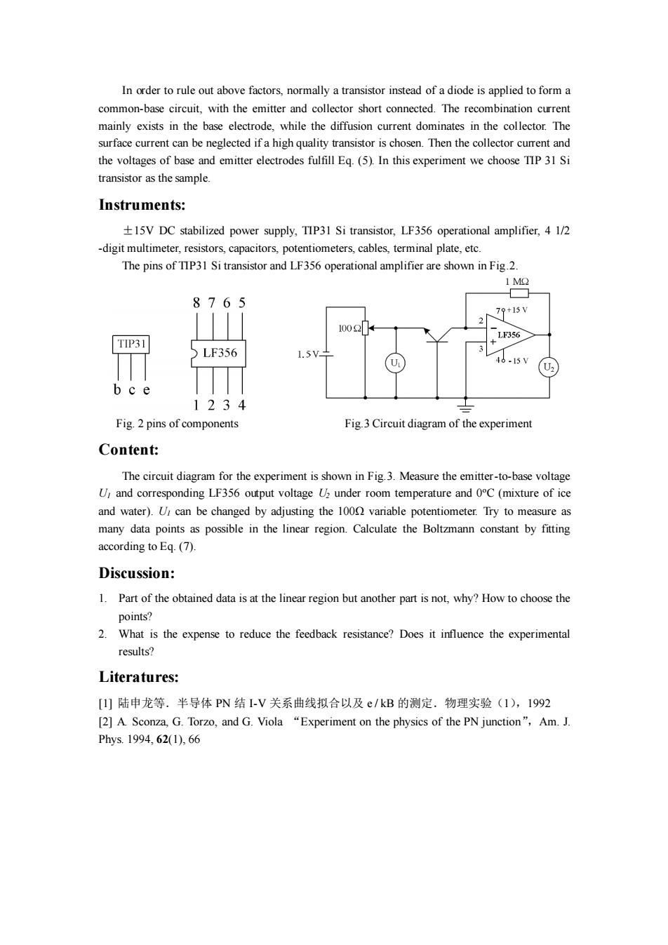
In order to rule out above factors,normally a transistor instead of a diode is applied to form a common-base circuit,with the emitter and collector short connected.The recombination current mainly exists in the base electrode,while the diffusion current dominates in the collector.The surface current can be neglected if a high quality transistor is chosen.Then the collector current and the voltages of base and emitter electrodes fulfill Eq.(5).In this experiment we choose TIP 31 Si transistor as the sample. Instruments: 15V DC stabilized power supply,TIP31 Si transistor,LF356 operational amplifier,4 1/2 -digit multimeter,resistors,capacitors,potentiometers,cables,terminal plate,etc. The pins of TIP31 Si transistor and LF356 operational amplifier are shown in Fig.2. 1 MO 8765 79+15V 1002 LF356 TIP31 LF356 1.5 15V bce 1234 Fig.2 pins of components Fig.3 Circuit diagram of the experiment Content: The circuit diagram for the experiment is shown in Fig.3.Measure the emitter-to-base voltage U and corresponding LF356 output voltage U under room temperature and 0C(mixture of ice and water).U,can be changed by adjusting the 1000 variable potentiometer.Try to measure as many data points as possible in the linear region.Calculate the Boltzmann constant by fitting according to Eq.(7). Discussion: 1.Part of the obtained data is at the linear region but another part is not,why?How to choose the points? 2.What is the expense to reduce the feedback resistance?Does it influence the experimental results? Literatures: [1]陆申龙等.半导体PN结I-V关系曲线拟合以及e/kB的测定.物理实验(1),1992 [2]A.Sconza,G.Torzo,and G.Viola "Experiment on the physics of the PN junction",Am.J. Phys.1994,62(1),66
In order to rule out above factors, normally a transistor instead of a diode is applied to form a common-base circuit, with the emitter and collector short connected. The recombination current mainly exists in the base electrode, while the diffusion current dominates in the collector. The surface current can be neglected if a high quality transistor is chosen. Then the collector current and the voltages of base and emitter electrodes fulfill Eq. (5). In this experiment we choose TIP 31 Si transistor as the sample. Instruments: ±15V DC stabilized power supply, TIP31 Si transistor, LF356 operational amplifier, 4 1/2 -digit multimeter, resistors, capacitors, potentiometers, cables, terminal plate, etc. The pins of TIP31 Si transistor and LF356 operational amplifier are shown in Fig.2. Fig. 2 pins of components Fig.3 Circuit diagram of the experiment Content: The circuit diagram for the experiment is shown in Fig.3. Measure the emitter-to-base voltage U1 and corresponding LF356 output voltage U2 under room temperature and 0oC (mixture of ice and water). U1 can be changed by adjusting the 100Ω variable potentiometer. Try to measure as many data points as possible in the linear region. Calculate the Boltzmann constant by fitting according to Eq. (7). Discussion: 1. Part of the obtained data is at the linear region but another part is not, why? How to choose the points? 2. What is the expense to reduce the feedback resistance? Does it influence the experimental results? Literatures: [1] 陆申龙等.半导体 PN 结 I-V 关系曲线拟合以及 e / kB 的测定.物理实验(1),1992 [2] A. Sconza, G. Torzo, and G. Viola “Experiment on the physics of the PN junction”,Am. J. Phys. 1994, 62(1), 66