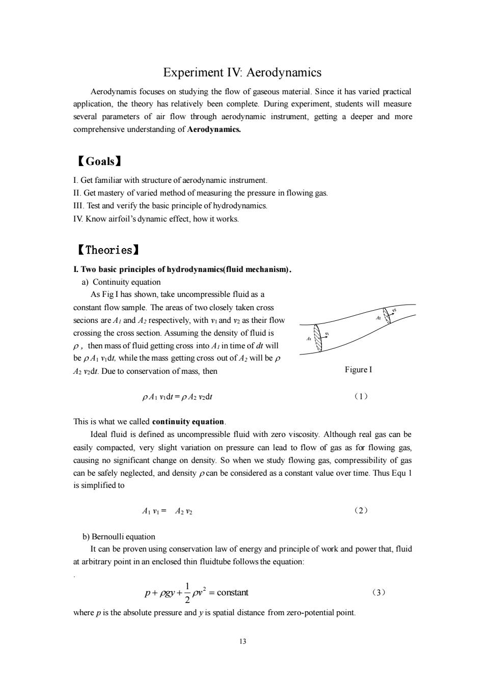
Experiment IV:Aerodynamics Aerodynamis focuses on studying the flow of gaseous material.Since it has varied practical application,the theory has relatively been complete.During experiment,students will measure several parameters of air flow through aerodynamic instrument,getting a deeper and more comprehensive understanding of Aerodynamics. 【Goals】 I.Get familiar with structure of aerodynamic instrument. II.Get mastery of varied method of measuring the pressure in flowing gas. III.Test and verify the basic principle of hydrodynamics. IV.Know airfoil's dynamic effect,how it works. 【Theories】 L.Two basic principles of hydrodynamics(fluid mechanism). a)Continuity equation As Fig I has shown,take uncompressible fluid as a constant flow sample.The areas of two closely taken cross secions are A/and A2 respectively,with vi and v2 as their flow crossing the cross section.Assuming the density of fluid is P,then mass of fluid getting cross into A in time of dt will be pA vidt,while the mass getting cross out of A2 will be p A2 vadt.Due to conservation of mass,then Figure I pA1 vidt=pA2 vadt (1) This is what we called continuity equation. Ideal fluid is defined as uncompressible fluid with zero viscosity.Although real gas can be easily compacted,very slight variation on pressure can lead to flow of gas as for flowing gas, causing no significant change on density.So when we study flowing gas,compressibility of gas can be safely neglected,and density pcan be considered as a constant value over time.Thus Equ 1 is simplified to A1V1=A22 (2) b)Bernoulli equation It can be proven using conservation law of energy and principle of work and power that,fluid at arbitrary point in an enclosed thin fluidtube follows the equation: 1 constant (3) where p is the absolute pressure and y is spatial distance from zero-potential point. 3
13 Experiment IV: Aerodynamics Aerodynamis focuses on studying the flow of gaseous material. Since it has varied practical application, the theory has relatively been complete. During experiment, students will measure several parameters of air flow through aerodynamic instrument, getting a deeper and more comprehensive understanding of Aerodynamics. 【Goals】 I. Get familiar with structure of aerodynamic instrument. II. Get mastery of varied method of measuring the pressure in flowing gas. III. Test and verify the basic principle of hydrodynamics. IV. Know airfoil’s dynamic effect, how it works. 【Theories】 I. Two basic principles of hydrodynamics(fluid mechanism). a) Continuity equation As Fig I has shown, take uncompressible fluid as a constant flow sample. The areas of two closely taken cross secions are A1 and A2 respectively, with v1 and v2 as their flow crossing the cross section. Assuming the density of fluid is then mass of fluid getting cross into A1 in time of dt will be A1 v1dt, while the mass getting cross out of A2 will be A2 v2dt. Due to conservation of mass, then A1 v1dt = A2 v2dt (1) This is what we called continuity equation. Ideal fluid is defined as uncompressible fluid with zero viscosity. Although real gas can be easily compacted, very slight variation on pressure can lead to flow of gas as for flowing gas, causing no significant change on density. So when we study flowing gas, compressibility of gas can be safely neglected, and density can be considered as a constant value over time. Thus Equ 1 is simplified to A1 v1 = A2 v2 (2) b) Bernoulli equation It can be proven using conservation law of energy and principle of work and power that, fluid at arbitrary point in an enclosed thin fluidtube follows the equation: . constant 2 1 2 p + gy + v = (3) where p is the absolute pressure and y is spatial distance from zero-potential point. v1 A1 A2 v2 Figure I

II.Measuring fluid pressure Fig 2 shows the schematic of measuring pressure of flowing fluid.Measured pressure p in Fig 2-(1)and 2-(2)is called static pressure,while p in Fig 2-(3)is called total pressure which follows p'=p+(1/2)pv Usually the pressure Ap measured in Fig 2-(4)is called dynamical pressure,which follows Ap=p-p=(1/2)pv. Derived from Bernoulli equation,speed of fluid can be written as: Ap (4) Experimental instrument will be put in wind tunnel.Thus pin equations refers to air density inside tunnel.Under standard air status,the density of dry air is p=1.293 kg/m.In equations,p is the dynamical pressure measured by pressure sensor,while v is wind speed at the position where the sensor is. 而行司 3 4) Figure 2 III.Some knowledges of aerophysics Fig 3 shows the cross section of wing of an air plane and the air flow line around it.As you can see on figure,a region of air with high fluid flow and low pressure will be formed above the wing,while air below wing remains the same status as surrounding atomsphere.So wings not only get resistent force Fw,which holds opposite direction as air plane motion,during a flight,but also get Figure 3 an upward force Fa which is perpendicular to motion.With fixed speed of plane, magnitudes of these two forces depend on a(angle of flying direction over horizontal line). 14
14 II. Measuring fluid pressure Fig 2 shows the schematic of measuring pressure of flowing fluid. Measured pressure p in Fig 2-(1) and 2-(2) is called static pressure, while p’ in Fig 2-(3) is called total pressure which follows p’=p+(1/2) . Usually the pressure p measured in Fig 2-(4) is called dynamical pressure, which follows p=p’ -p=(1/2). Derived from Bernoulli equation, speed of fluid can be written as: p v = (4) Experimental instrument will be put in wind tunnel. Thus in equations refers to air density inside tunnel. Under standard air status, the density of dry air is = kg/m3 . In equations, p is the dynamical pressure measured by pressure sensor, while is wind speed at the position where the sensor is. III. Some knowledges of aerophysics Fig 3 shows the cross section of wing of an air plane and the air flow line around it. As you can see on figure, a region of air with high fluid flow and low pressure will be formed above the wing, while air below wing remains the same status as surrounding atomsphere. So wings not only get resistent force FW, which holds opposite direction as air plane motion, during a flight, but also get an upward force Fa which is perpendicular to motion. With fixed speed of plane, magnitudes of these two forces depend on (angle of flying direction over horizontal line). p p P' (1) (2) (3) (4) Figure 2 a Fa Fw Figure 3
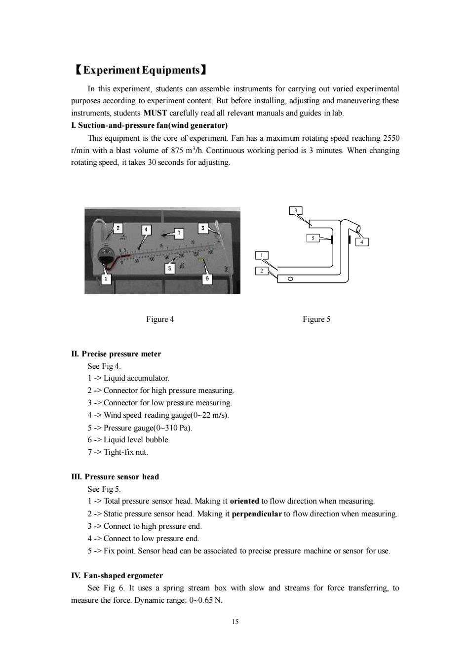
【Experiment Equipments】 In this experiment,students can assemble instruments for carrying out varied experimental purposes according to experiment content.But before installing,adjusting and maneuvering these instruments,students MUST carefully read all relevant manuals and guides in lab L Suction-and-pressure fan(wind generator) This equipment is the core of experiment.Fan has a maximum rotating speed reaching 2550 r/min with a blast volume of 875 m3/h.Continuous working period is 3 minutes.When changing rotating speed,it takes 30 seconds for adjusting. Figure 4 Figure 5 II.Precise pressure meter See Fig 4. 1->Liquid accumulator. 2->Connector for high pressure measuring. 3->Connector for low pressure measuring. 4->Wind speed reading gauge(0~22 m/s). 5->Pressure gauge(0~310 Pa). 6->Liquid level bubble. 7->Tight-fix nut. III.Pressure sensor head See Fig 5. 1->Total pressure sensor head.Making it oriented to flow direction when measuring. 2->Static pressure sensor head.Making it perpendicular to flow direction when measuring. 3->Connect to high pressure end. 4->Connect to low pressure end. 5->Fix point.Sensor head can be associated to precise pressure machine or sensor for use. IV.Fan-shaped ergometer See Fig 6.It uses a spring stream box with slow and streams for force transferring,to measure the force.Dynamic range:0~0.65 N. 公
15 【Experiment Equipments】 In this experiment, students can assemble instruments for carrying out varied experimental purposes according to experiment content. But before installing, adjusting and maneuvering these instruments, students MUST carefully read all relevant manuals and guides in lab. I. Suction-and-pressure fan(wind generator) This equipment is the core of experiment. Fan has a maximum rotating speed reaching 2550 r/min with a blast volume of 875 m3 /h. Continuous working period is 3 minutes. When changing rotating speed, it takes 30 seconds for adjusting. II. Precise pressure meter See Fig 4. 1 -> Liquid accumulator. 2 -> Connector for high pressure measuring. 3 -> Connector for low pressure measuring. 4 -> Wind speed reading gauge(0~22 m/s). 5 -> Pressure gauge(0~310 Pa). 6 -> Liquid level bubble. 7 -> Tight-fix nut. III. Pressure sensor head See Fig 5. 1 -> Total pressure sensor head. Making it oriented to flow direction when measuring. 2 -> Static pressure sensor head. Making it perpendicular to flow direction when measuring. 3 -> Connect to high pressure end. 4 -> Connect to low pressure end. 5 -> Fix point. Sensor head can be associated to precise pressure machine or sensor for use. IV. Fan-shaped ergometer See Fig 6. It uses a spring stream box with slow and streams for force transferring, to measure the force. Dynamic range: 0~0.65 N. Figure 4 1 5 4 3 2 Figure 5
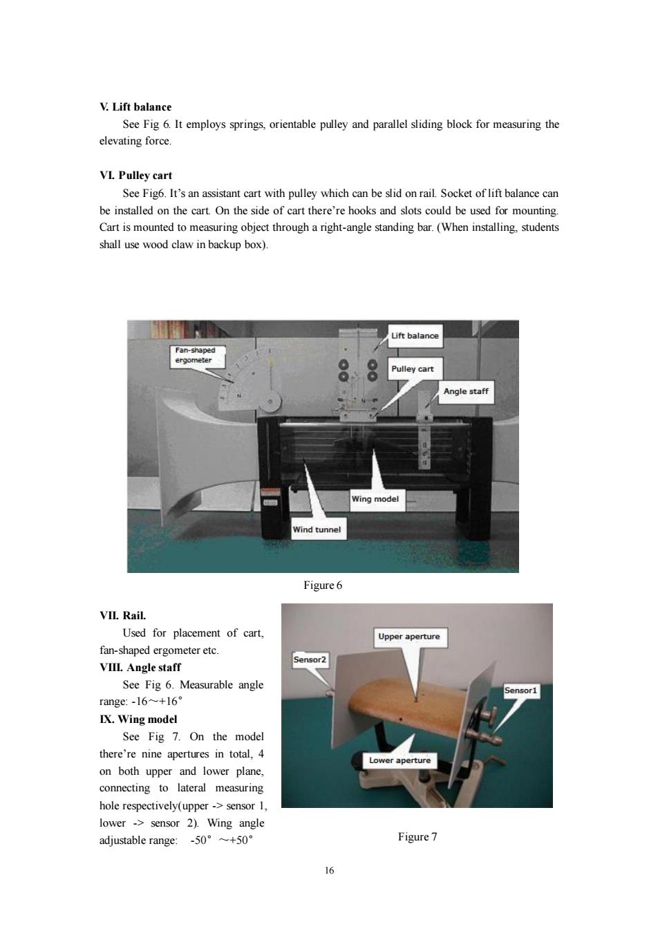
V.Lift balance See Fig 6.It employs springs,orientable pulley and parallel sliding block for measuring the elevating force. VI.Pulley cart See Fig6.It's an assistant cart with pulley which can be slid on rail.Socket of lift balance can be installed on the cart.On the side of cart there're hooks and slots could be used for mounting. Cart is mounted to measuring object through a right-angle standing bar.(When installing,students shall use wood claw in backup box). Lift balance Fan-shaped ergometer Pulley cart Angle staff Wing model Wind tunnel Figure 6 VIL.Rail. Used for placement of cart, Upper aperture fan-shaped ergometer etc. Sensor2 VIIL.Angle staff See Fig 6.Measurable angle Sensor1 range:-l6~+16° IX.Wing model See Fig 7.On the model there're nine apertures in total,4 Lower aperture on both upper and lower plane, connecting to lateral measuring hole respectively(upper->sensor 1, lower -sensor 2).Wing angle adjustable range:-50°+50° Figure 7 16
16 V. Lift balance See Fig 6. It employs springs, orientable pulley and parallel sliding block for measuring the elevating force. VI. Pulley cart See Fig6. It’s an assistant cart with pulley which can be slid on rail. Socket of lift balance can be installed on the cart. On the side of cart there’re hooks and slots could be used for mounting. Cart is mounted to measuring object through a right-angle standing bar. (When installing, students shall use wood claw in backup box). VII. Rail. Used for placement of cart, fan-shaped ergometer etc. VIII. Angle staff See Fig 6. Measurable angle range: -16~+16° IX. Wing model See Fig 7. On the model there’re nine apertures in total, 4 on both upper and lower plane, connecting to lateral measuring hole respectively(upper -> sensor 1, lower -> sensor 2). Wing angle adjustable range: -50°~+50° Figure 6 Figure 7
【Experiment Contents】 L Wind tunnel experiment a)Test and verify continuity equation Install a glass cover behind wind machine,serving as a wind tunnel.Put rail on it,and an oblique base beneath.Use pressure sensor head associated with precise pressure meter,to measure dynamic pressure Ap and wind speed vo at each marked spot.Students need to further calculate the flow at each marked spot based on the measurement,testing and verifying continuity equation. b)Test the wing model Mount the wing model under cart inside wind tunnel.It will be necessary to install airproof rail on wind path.In the mean time,insert angle staff(See Fig 6),and use fan-shaped ergometer and lift balance sensor 1.During measurement,change the wing angle from +12to 8.With every 2,students shall measure the resistent force Fw and elevating force Fa.Before starting measuring,students shall set wing angle to +12,and then adjust the wind speed to make the resistent force to be around 2N.Draw the plot of Fw verse Fa according to data measured,and estimate the optimal angle for plane taking off. II.Open-tunnel experiment. A)Put wing model right behind wind generator,with sensor head symmetrically located on the side and connected to pressure meter.Change the wing angle(every 10 get a measurement), measure the pressure difference between wing upper and lower region. B)Relocate sensor head and do above step once more. C)Plot the relationship between wing angle and pressure difference.Based on that estimate the optimal angle for plane to take off.Illustrate your reason. 【Attentions.】 I.Some parts are very thin and fragile.Be cautious about the way you put force when installing and uninstalling cart and ergometer. II.There should be some space between suction port of wind generator and wind tunnel inlet. DONOT let wind machine(generator)keep working for more than 3 minutes. III.The liquid inside precise pressure meter is very special and dedicated to that type of meter. Please be careful to not spill it out when installing.Also please cover the rim of tube when not using. IV.Make sure not to overload the fan-shaped ergometer and lift balance. 17
17 【Experiment Contents】 I. Wind tunnel experiment a) Test and verify continuity equation Install a glass cover behind wind machine, serving as a wind tunnel. Put rail on it, and an oblique base beneath. Use pressure sensor head associated with precise pressure meter, to measure dynamic pressure p and wind speed v0 at each marked spot. Students need to further calculate the flow at each marked spot based on the measurement, testing and verifying continuity equation. b) Test the wing model Mount the wing model under cart inside wind tunnel. It will be necessary to install airproof rail on wind path. In the mean time, insert angle staff(See Fig 6), and use fan-shaped ergometer and lift balance sensor 1. During measurement, change the wing angle from +12°to 8°. With every 2°, students shall measure the resistent force FW and elevating force Fa. Before starting measuring, students shall set wing angle to +12°, and then adjust the wind speed to make the resistent force to be around 2N. Draw the plot of FW verse Fa according to data measured, and estimate the optimal angle for plane taking off. II. Open-tunnel experiment. A) Put wing model right behind wind generator, with sensor head symmetrically located on the side and connected to pressure meter. Change the wing angle(every 10° get a measurement), measure the pressure difference between wing upper and lower region. B) Relocate sensor head and do above step once more. C) Plot the relationship between wing angle and pressure difference. Based on that estimate the optimal angle for plane to take off. Illustrate your reason. 【Attentions】 I. Some parts are very thin and fragile. Be cautious about the way you put force when installing and uninstalling cart and ergometer. II. There should be some space between suction port of wind generator and wind tunnel inlet. DONOT let wind machine(generator) keep working for more than 3 minutes. III. The liquid inside precise pressure meter is very special and dedicated to that type of meter. Please be careful to not spill it out when installing. Also please cover the rim of tube when not using. IV. Make sure not to overload the fan-shaped ergometer and lift balance
【References】 [1]金仲辉,梁德余.大学物理教程.北京:科学出版社.2000.5 [2]张也影.流体力学.北京:高等教育出版社.1999.6 [3]陆廷济,胡德敬,陈铭南主编.物理实验教程.上海:同济大学出版社.2000.9 8
18 【References】 [1] 金仲辉,梁德余.大学物理教程.北京:科学出版社.2000.5 [2] 张也影.流体力学.北京:高等教育出版社.1999.6 [3] 陆廷济,胡德敬,陈铭南主编.物理实验教程.上海:同济大学出版社.2000.9