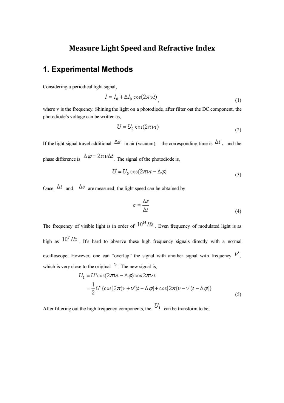
Measure Light Speed and Refractive Index 1.Experimental Methods Considering a periodical light signal, 1=1+Alo cos(2πvt) (1) where v is the frequency.Shining the light on a photodiode,after filter out the DC component,the photodiode's voltage can be written as, U=Un cos(27vt) (2) If the light signal travel additionalin air(vacuum),the comresponding time is,and the phase differeciThe signal of the photodiodes U=U,cos(2πvt-△0) (3) Once and s are measured,the light speed can be obtained by △s C= At (4) The frequency of visible light is in order of1Even frequency of modulated light isas high as10 It's hard to observe these high frequency signals directly with a normal oscilloscope.However,one can "overlap"the signal with another signal with frequency which is very close to the original The new signal is, U1=U'cos(2πvt-△g)cos2rVt 1 =5U'(cos[2πv+v't-△]+cos[2πv-v')t-△g]0 (5) Aferfteringout the high frequeney compoents,thecan be transformtobe
Measure Light Speed and Refractive Index 1. Experimental Methods Considering a periodical light signal, , (1) where v is the frequency. Shining the light on a photodiode, after filter out the DC component, the photodiode’s voltage can be written as, (2) If the light signal travel additional in air (vacuum), the corresponding time is ,and the phase difference is . The signal of the photodiode is, (3) Once and are measured, the light speed can be obtained by (4) The frequency of visible light is in order of . Even frequency of modulated light is as high as . It’s hard to observe these high frequency signals directly with a normal oscilloscope. However, one can “overlap” the signal with another signal with frequency , which is very close to the original . The new signal is, (5) After filtering out the high frequency components, the can be transform to be

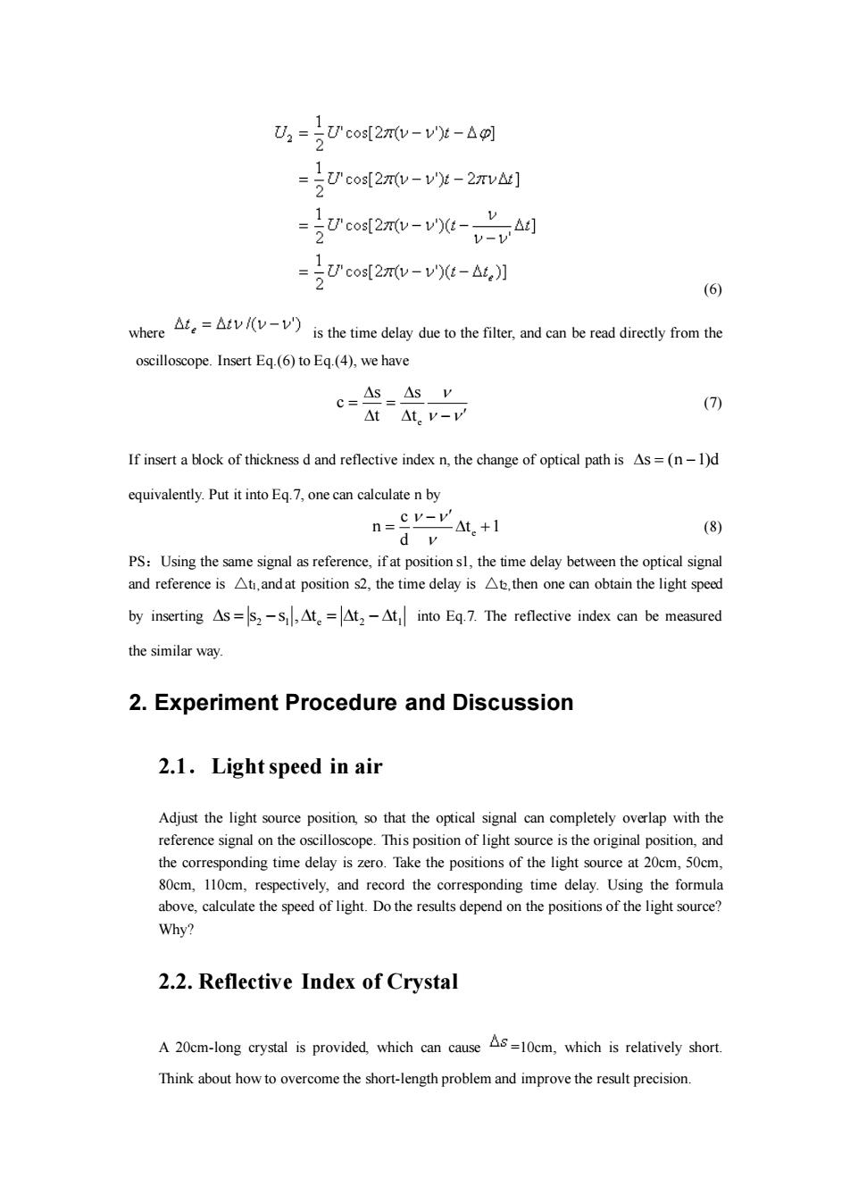
=Ucos[27(v-v)-6 =号'cos[2w-v'g-2Tv1 cos[2(v-v)-v Δ] 2 =v' =2U"cos2xw-vt-a,】 (6) where)is the time delay due to the filter,and can be read direectly from the oscilloscope.Insert Eq.(6)to Eq.(4),we have C=As=As v (7) At△t.v-v If insert a block of thickness d and reflective index n,the change of optical path is As=(n-1)d equivalently.Put it into Eq.7,one can calculate n by n=cv-v △t.+1 (8) PS:Using the same signal as reference,if at position sl,the time delay between the optical signal and reference is At,and at position s2,the time delay is At.then one can obtain the light speed by inserting As=s2-S,At.=At2-At into Eq.7.The reflective index can be measured the similar way. 2.Experiment Procedure and Discussion 2.1.Light speed in air Adjust the light source position,so that the optical signal can completely overlap with the reference signal on the oscilloscope.This position of light source is the original position,and the corresponding time delay is zero.Take the positions of the light source at 20cm,50cm, 80cm,110cm,respectively,and record the corresponding time delay.Using the formula above,calculate the speed of light.Do the results depend on the positions of the light source? Why? 2.2.Reflective Index of Crystal A 20cm-long crystal is provided,which can cause =10cm,which is relatively short. Think about how to overcome the short-length problem and improve the result precision
(6) where is the time delay due to the filter, and can be read directly from the oscilloscope. Insert Eq.(6) to Eq.(4), we have e s s c t t = = − (7) If insert a block of thickness d and reflective index n, the change of optical path is = − s (n 1)d equivalently. Put it into Eq.7, one can calculate n by e c n t 1 d − = + (8) PS:Using the same signal as reference, if at position s1, the time delay between the optical signal and reference is △t1, and at position s2, the time delay is △t2, then one can obtain the light speed by inserting 2 1 e 2 1 = − = − s s s , t t t into Eq.7. The reflective index can be measured the similar way. 2. Experiment Procedure and Discussion 2.1.Light speed in air Adjust the light source position, so that the optical signal can completely overlap with the reference signal on the oscilloscope. This position of light source is the original position, and the corresponding time delay is zero. Take the positions of the light source at 20cm, 50cm, 80cm, 110cm, respectively, and record the corresponding time delay. Using the formula above, calculate the speed of light. Do the results depend on the positions of the light source? Why? 2.2. Reflective Index of Crystal A 20cm-long crystal is provided, which can cause =10cm, which is relatively short. Think about how to overcome the short-length problem and improve the result precision

2.3.Reflective Index of Water The similar problem shown above may appear here too.Furthermore,the water container may case problem either.How to avoid that? 3.Instruments and Cautions 3.1.Instruments 3.2.Hints Since the peak value and zero position are determined manually,you may want to adjust the signal of the digital oscilloscope,so that the peak height of the optical signal is the same as that of the reference signal
2.3.Reflective Index of Water The similar problem shown above may appear here too. Furthermore, the water container may case problem either. How to avoid that? 3. Instruments and Cautions 3.1.Instruments 3.2.Hints Since the peak value and zero position are determined manually, you may want to adjust the signal of the digital oscilloscope, so that the peak height of the optical signal is the same as that of the reference signal