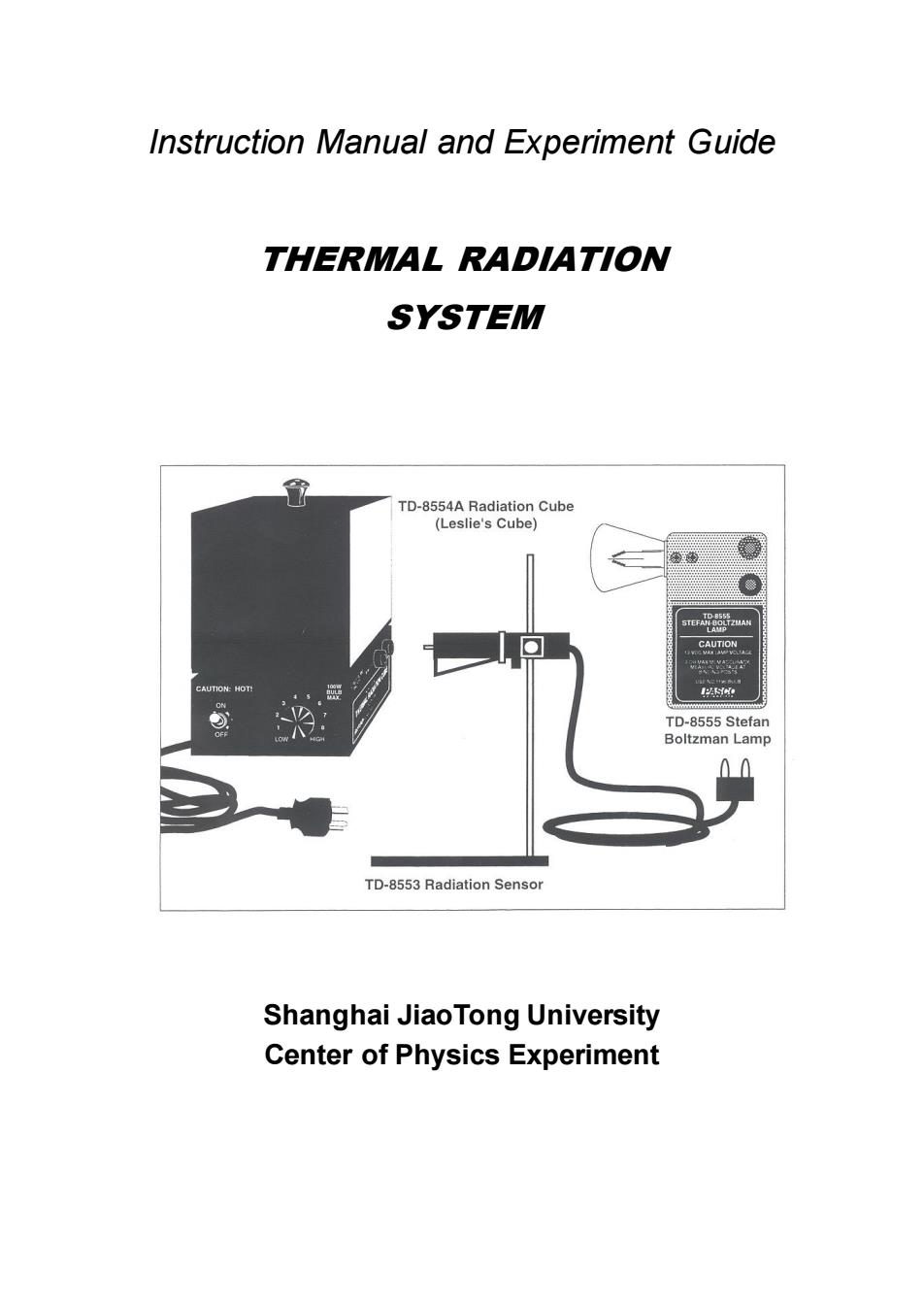
Instruction Manual and Experiment Guide THERMAL RADIATION SYSTEM TD-8554A Radiation Cube (Leslie's Cube) se器wa CAUTION CAUTION:HOT! IISiNe TD-8555 Stefan Boltzman Lamp 0 TD-8553 Radiation Sensor Shanghai JiaoTong University Center of Physics Experiment
Instruction Manual and Experiment Guide THERMAL RADIATION SYSTEM Shanghai JiaoTong University Center of Physics Experiment
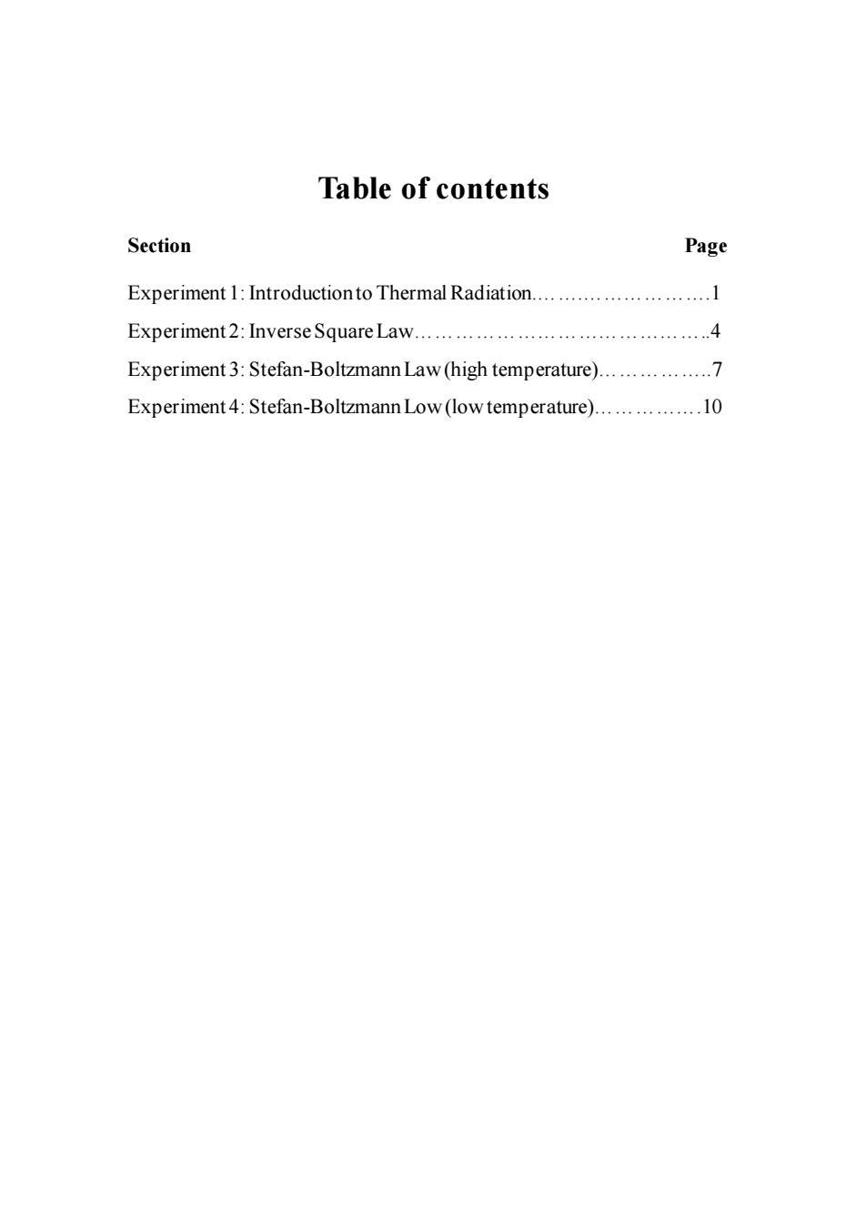
Table of contents Section Page Experiment 1:Introductionto Thermal Radiation...........................1 Experiment 2:InverseSquare Law................4 Experiment 3:Stefan-Boltzmann Law (high temperature)................. Experiment4:Stefan-Boltzmann Low(lowtemperature)................10
Table of contents Section Page Experiment 1: Introduction to Thermal Radiation.…….……………….1 Experiment 2: Inverse Square Law……………………………………..4 Experiment 3: Stefan-Boltzmann Law (high temperature)……………..7 Experiment 4: Stefan-Boltzmann Low (low temperature)…………….10
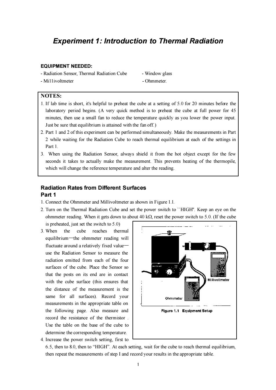
Experiment 1:Introduction to Thermal Radiation EQUIPMENT NEEDED: -Radiation Sensor,Thermal Radiation Cube -Window glass -Millivoltmeter -Ohmmeter. NOTES: 1.If lab time is short,it's helpful to preheat the cube at a setting of 5.0 for 20 minutes before the laboratory period begins.(A very quick method is to preheat the cube at full power for 45 minutes,then use a small fan to reduce the temperature quickly as you lower the power input. Just be sure that equilibrium is attained with the fan off.) 2.Part I and 2 of this experiment can be performed simultaneously.Make the measurements in Part 2 while waiting for the Radiation Cube to reach thermal equilibrium at each of the settings in Part 1. 3.When using the Radiation Sensor,always shield it from the hot object except for the few seconds it takes to actually make the measurement.This prevents heating of the thermopile, which will change the reference temperature and alter the reading. Radiation Rates from Different Surfaces Part 1 1.Connect the Ohmmeter and Millivoltmeter as shown in Figure 1.1. 2.Turn on the Thermal Radiation Cube and set the power switch to"HIGH".Keep an eye on the ohmmeter reading.When it gets down to about 40 k,reset the power switch to 5.0.(If the cube is preheated,just set the switch to 5.0) 3.When the cube reaches thermal equilibrium-the ohmmeter reading will fluctuate around a relatively fixed value- use the Radiation Sensor to measure the radiation emitted from each of the four surfaces of the cube.Place the Sensor so that the posts on its end are in contact with the cube surface (this ensures that Milvoltmeter the distance of the measurement is the same for all surfaces).Record your measurements in the appropriate table on the following page.Also measure and Figure 1.1 Equipmant Setup record the resistance of the thermistor. Use the table on the base of the cube to determine the corresponding temperature. 4.Increase the power switch setting,first to 6.5,then to 8.0,then to"HIGH".At each setting,wait for the cube to reach thermal equilibrium, then repeat the measurements of step I and record your results in the appropriate table
1 Experiment 1: Introduction to Thermal Radiation EQUIPMENT NEEDED: - Radiation Sensor, Thermal Radiation Cube - Window glass - Mi11ivoltmeter - Ohmmeter. NOTES: 1. If lab time is short, it's helpful to preheat the cube at a setting of 5.0 for 20 minutes before the laboratory period begins. (A very quick method is to preheat the cube at full power for 45 minutes, then use a small fan to reduce the temperature quickly as you lower the power input. Just be sure that equilibrium is attained with the fan off.) 2. Part 1 and 2 of this experiment can be performed simultaneously. Make the measurements in Part 2 while waiting for the Radiation Cube to reach thermal equilibrium at each of the settings in Part 1. 3. When using the Radiation Sensor, always shield it from the hot object except for the few seconds it takes to actually make the measurement. This prevents heating of the thermopile, which will change the reference temperature and alter the reading. Radiation Rates from Different Surfaces Part 1 1. Connect the Ohmmeter and Millivoltmeter as shown in Figure 1.l. 2. Turn on the Thermal Radiation Cube and set the power switch to ``HIGH''. Keep an eye on the ohmmeter reading. When it gets down to about 40 kΩ, reset the power switch to 5.0. (If the cube is preheated, just set the switch to 5.0) 3. When the cube reaches thermal equilibrium—the ohmmeter reading will fluctuate around a relatively fixed value— use the Radiation Sensor to measure the radiation emitted from each of the four surfaces of the cube. Place the Sensor so that the posts on its end are in contact with the cube surface (this ensures that the distance of the measurement is the same for all surfaces). Record your measurements in the appropriate table on the following page. Also measure and record the resistance of the thermistor . Use the table on the base of the cube to determine the corresponding temperature. 4. Increase the power switch setting, first to 6.5, then to 8.0, then to “HIGH”. At each setting, wait for the cube to reach thermal equilibrium, then repeat the measurements of step I and record your results in the appropriate table
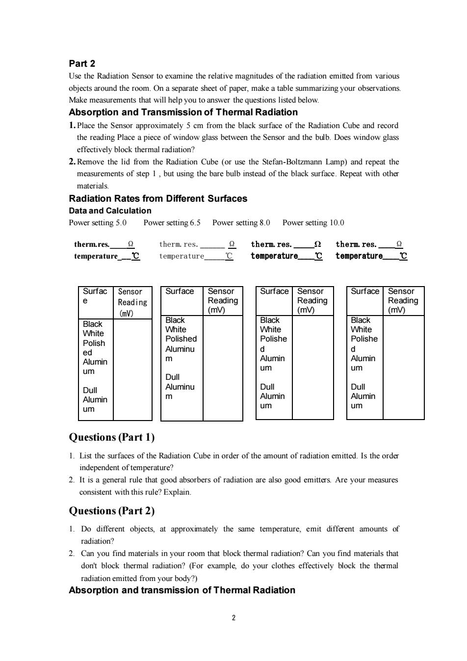
Part 2 Use the Radiation Sensor to examine the relative magnitudes of the radiation emitted from various objects around the room.On a separate sheet of paper,make a table summarizing your observations. Make measurements that will help you to answer the questions listed below. Absorption and Transmission of Thermal Radiation 1.Place the Sensor approximately 5 cm from the black surface of the Radiation Cube and record the reading Place a piece of window glass between the Sensor and the bulb.Does window glass effectively block thermal radiation? 2.Remove the lid from the Radiation Cube (or use the Stefan-Boltzmann Lamp)and repeat the measurements of step 1,but using the bare bulb instead of the black surface.Repeat with other materials Radiation Rates from Different Surfaces Data and Calculation Power setting 5.0 Power setting 6.5 Power setting 8.0 Power setting 10.0 therm.res.】 2 therm.res. therm.res. therm.res. temperature_℃ temperature temperature_℃ temperature.℃ Surfac Sensor Surface Sensor Surface Sensor Surface Sensor 0 Reading Reading Reading Reading (mV) (m) (mV) (m) Black Black Black Black White White White White Polished Polishe Polishe Polish ed Aluminu d d Alumin m Alumin Alumin um um um Dull Dull Aluminu Dull Dull Alumin m Alumin Alumin um um um Questions(Part 1) 1.List the surfaces of the Radiation Cube in order of the amount of radiation emitted.Is the order independent of temperature? 2.It is a general rule that good absorbers of radiation are also good emitters.Are your measures consistent with this rule?Explain. Questions(Part 2) 1.Do different objects,at approximately the same temperature,emit different amounts of radiation? 2.Can you find materials in your room that block thermal radiation?Can you find materials that don't block thermal radiation?(For example,do your clothes effectively block the thermal radiation emitted from your body?) Absorption and transmission of Thermal Radiation
2 Part 2 Use the Radiation Sensor to examine the relative magnitudes of the radiation emitted from various objects around the room. On a separate sheet of paper, make a table summarizing your observations. Make measurements that will help you to answer the questions listed below. Absorption and Transmission of Thermal Radiation 1. Place the Sensor approximately 5 cm from the black surface of the Radiation Cube and record the reading Place a piece of window glass between the Sensor and the bulb. Does window glass effectively block thermal radiation? 2.Remove the lid from the Radiation Cube (or use the Stefan-Boltzmann Lamp) and repeat the measurements of step 1 , but using the bare bulb instead of the black surface. Repeat with other materials. Radiation Rates from Different Surfaces Data and Calculation Power setting 5.0 Power setting 6.5 Power setting 8.0 Power setting 10.0 Questions (Part 1) 1. List the surfaces of the Radiation Cube in order of the amount of radiation emitted. Is the order independent of temperature? 2. It is a general rule that good absorbers of radiation are also good emitters. Are your measures consistent with this rule? Explain. Questions (Part 2) 1. Do different objects, at approximately the same temperature, emit different amounts of radiation? 2. Can you find materials in your room that block thermal radiation? Can you find materials that don't block thermal radiation? (For example, do your clothes effectively block the thermal radiation emitted from your body?) Absorption and transmission of Thermal Radiation therm.res.____Ω temperature___℃ therm.res.______ Ω temperature_____℃ therm.res._____Ω temperature____℃ therm.res.____Ω temperature____℃ Surfac e Sensor Reading (mV) Black White Polish ed Alumin um Dull Alumin um Surface Sensor Reading (mV) Black White Polished Aluminu m Dull Aluminu m Surface Sensor Reading (mV) Black White Polishe d Alumin um Dull Alumin um Surface Sensor Reading (mV) Black White Polishe d Alumin um Dull Alumin um

Questions 1.What do your results suggest about the phenomenon of heat loss through windows? 2.What do your results suggest about the Greenhouse Effect?
3 Questions 1. What do your results suggest about the phenomenon of heat loss through windows? 2. What do your results suggest about the Greenhouse Effect?
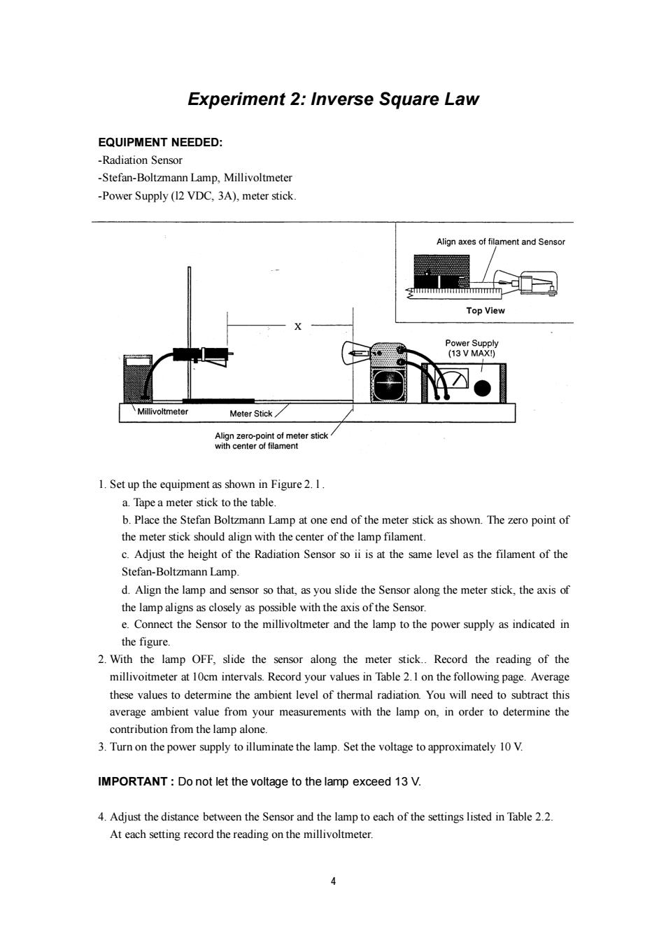
Experiment 2:Inverse Square Law EQUIPMENT NEEDED: -Radiation Sensor -Stefan-Boltzmann Lamp,Millivoltmeter -Power Supply(12 VDC,3A),meter stick. Align axes of filament and Sensor ghmmmmmmmimmmmm Top View Power Supply (13V MAX!) Millivoltmeter Meter Stick Align zero-point of meter stick with center of filament 1.Set up the equipment as shown in Figure 2.I a.Tape a meter stick to the table. b.Place the Stefan Boltzmann Lamp at one end of the meter stick as shown.The zero point of the meter stick should align with the center of the lamp filament. c.Adjust the height of the Radiation Sensor so ii is at the same level as the filament of the Stefan-Boltzmann Lamp. d.Align the lamp and sensor so that,as you slide the Sensor along the meter stick,the axis of the lamp aligns as closely as possible with the axis of the Sensor. e.Connect the Sensor to the millivoltmeter and the lamp to the power supply as indicated in the figure. 2.With the lamp OFF,slide the sensor along the meter stick..Record the reading of the millivoitmeter at 10cm intervals.Record your values in Table 2.1 on the following page.Average these values to determine the ambient level of thermal radiation.You will need to subtract this average ambient value from your measurements with the lamp on,in order to determine the contribution from the lamp alone. 3.Turn on the power supply to illuminate the lamp.Set the voltage to approximately 10 V. IMPORTANT:Do not let the voltage to the lamp exceed 13 V. 4.Adjust the distance between the Sensor and the lamp to each of the settings listed in Table 2.2. At each setting record the reading on the millivoltmeter
4 Experiment 2: Inverse Square Law EQUIPMENT NEEDED: -Radiation Sensor -Stefan-Boltzmann Lamp, Millivoltmeter -Power Supply (l2 VDC, 3A), meter stick. 1. Set up the equipment as shown in Figure 2. l . a. Tape a meter stick to the table. b. Place the Stefan Boltzmann Lamp at one end of the meter stick as shown. The zero point of the meter stick should align with the center of the lamp filament. c. Adjust the height of the Radiation Sensor so ii is at the same level as the filament of the Stefan-Boltzmann Lamp. d. Align the lamp and sensor so that, as you slide the Sensor along the meter stick, the axis of the lamp aligns as closely as possible with the axis of the Sensor. e. Connect the Sensor to the millivoltmeter and the lamp to the power supply as indicated in the figure. 2. With the lamp OFF, slide the sensor along the meter stick.. Record the reading of the millivoitmeter at 10cm intervals. Record your values in Table 2.1 on the following page. Average these values to determine the ambient level of thermal radiation. You will need to subtract this average ambient value from your measurements with the lamp on, in order to determine the contribution from the lamp alone. 3. Turn on the power supply to illuminate the lamp. Set the voltage to approximately 10 V. IMPORTANT : Do not let the voltage to the lamp exceed 13 V. 4. Adjust the distance between the Sensor and the lamp to each of the settings listed in Table 2.2. At each setting record the reading on the millivoltmeter

IMPORTANT:Make each reading quickly.Between reading from the lamp,or place the reflective heat shield between the lamp and the Sensor,so that the temperature of the Sensor stays relatively constant.. Table2.1 Table2.2 Ambient Radiation Level Radiation Level versus Distance X Ambient Radiation Rad 1 Rad-Ambient (cm) Level X (mV) (mV) (m) (cm) 10 (cm-2) 20 2.5 30 3.0 40 3.5 50 4.0 60 4.5 0 5.0 80 6.0 9 7.0 100 8.0 9.0 Average Ambient 10.0 Radiation Level 12.0 14.0 16.0 18.0 20.0 25.0 30.0 35.0 40.0 45.0 50.0 60.0 70.0 80.0 90.0 100.0 Calculations 1.For each value of X,calculate1/2.Enter your results in Table 2.2. 2.Subtract the Average Ambient Radiation Level from each of your Rad measurements in Table 2.2.Enter your results in the table. 3.On a separate sheet of paper,make a graph of Radiation Level versus Distance from Source, using columns one and four from Table 2.2.Let the radiation level be the dependent (y)axis. 6
5 IMPORTANT: Make each reading quickly. Between reading from the lamp, or place the reflective heat shield between the lamp and the Sensor, so that the temperature of the Sensor stays relatively constant. . X (cm) Rad (mV) 2 1 X ( ) −2 cm Rad-Ambient (mV) 2.5 3.0 3.5 4.0 4.5 5.0 6.0 7.0 8.0 9.0 10.0 12.0 14.0 16.0 18.0 20.0 25.0 30.0 35.0 40.0 45.0 50.0 60.0 70.0 80.0 90.0 100.0 Calculations 1. For each value of X, calculate 2 1/ X . Enter your results in Table 2.2. 2. Subtract the Average Ambient Radiation Level from each of your Rad measurements in Table 2.2. Enter your results in the table. 3. On a separate sheet of paper, make a graph of Radiation Level versus Distance from Source, using columns one and four from Table 2.2. Let the radiation level be the dependent (y) axis. X (cm) Ambient Radiation Level (mV) 10 20 30 40 50 60 70 80 90 100 Average Ambient Radiation Level = Table2.1 Ambient Radiation Level Table2.2 Radiation Level versus Distance
4.If your graph from part 3 is not linear,make a graph of Radiation Level versus 1/X2,using columns three and four from table 2.2. Questions 1.Which of the two graphs is more liner is it linear over the entire range of measurements? 2.The inverse square law states that the radiant energy per unit area emitted by a point source of radiation decreases as the square of the distance from the source to the point of detection.Does your data support this assertion? 3.Is the Stefan-Boltzmann Lamp truly a point source of radiation if not,how might this affect your results?Do you see such an effect in the data you have taken? 6
6 4. If your graph from part 3 is not linear, make a graph of Radiation Level versus 2 1/ X , using columns three and four from table 2.2. Questions 1. Which of the two graphs is more liner is it linear over the entire range of measurements? 2. The inverse square law states that the radiant energy per unit area emitted by a point source of radiation decreases as the square of the distance from the source to the point of detection. Does your data support this assertion? 3. Is the Stefan-Boltzmann Lamp truly a point source of radiation if not, how might this affect your results? Do you see such an effect in the data you have taken?
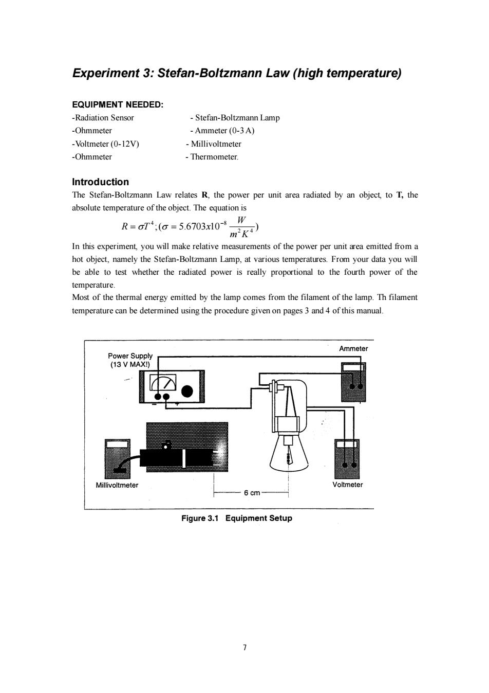
Experiment 3:Stefan-Boltzmann Law(high temperature) EQUIPMENT NEEDED: -Radiation Sensor -Stefan-Boltzmann Lamp -Ohmmeter -Ammeter(0-3A) -Voltmeter(0-12V) Millivoltmeter -Ohmmeter -Thermometer. Introduction The Stefan-Boltzmann Law relates R,the power per unit area radiated by an object,to T,the absolute temperature of the object.The equation is R=o7;(G=56703x108W ) In this experiment,you will make relative measurements of the power per unit area emitted from a hot object,namely the Stefan-Boltzmann Lamp,at various temperatures.From your data you will be able to test whether the radiated power is really proportional to the fourth power of the temperature. Most of the thermal energy emitted by the lamp comes from the filament of the lamp.Th filament temperature can be determined using the procedure given on pages 3 and 4 of this manual. Ammeter Power Supply (13 V MAX!) Millivoltmeter Voltmeter Figure 3.1 Equipment Setup >
7 Experiment 3: Stefan-Boltzmann Law (high temperature) EQUIPMENT NEEDED: -Radiation Sensor - Stefan-Boltzmann Lamp -Ohmmeter - Ammeter (0-3 A) -Voltmeter (0-12V) - Millivoltmeter -Ohmmeter - Thermometer. Introduction The Stefan-Boltzmann Law relates R, the power per unit area radiated by an object, to T, the absolute temperature of the object. The equation is ;( 5.6703 10 ) 2 4 4 8 m K W R T x − = = In this experiment, you will make relative measurements of the power per unit area emitted from a hot object, namely the Stefan-Boltzmann Lamp, at various temperatures. From your data you will be able to test whether the radiated power is really proportional to the fourth power of the temperature. Most of the thermal energy emitted by the lamp comes from the filament of the lamp. Th filament temperature can be determined using the procedure given on pages 3 and 4 of this manual
Procedure IMPORTANT:The voltage into the lam should NEVER exceed 13 V.Higher voltages will burn out the filament. 1.BEFORE TURNING ON THE LA MP,measure Tret the room temperature in degrees Kelvin, (K=C+273)and R the resistance of the filament of the Stefan-Boltzmann Lamp at room temperature.Enter your results in the spaces on the following page. 2.Set up the equipment as shown Figure 3.1.The voltmeter should be connected directly to the binding posts of the Stefan-Boltzmann Lamp.The Sensor should be at the same height as the filament,with the front face of the Sensor approximately 6 cm away from the filament.The entrance angle of the thermopile should include no close objects other than the lamp. 3.Turn on the power supply.Set the voltage,V,to each of the settings listed in Table 3.1 on the following page.At each voltage setting,record I,the ammeter reading and Rad,the reading on the millivoltmeter. IMPORTANT:Make each Sensor reading quickly.Between readings,place both sheet of insulating foam between the lamp and the Sensor,with the silvered surface facing the lamp,so that the temperature of the Sensor stays relatively constant
8 Procedure IMPORTANT: The voltage into the lam should NEVER exceed 13 V. Higher voltages will burn out the filament. 1. BEFORE TURNING ON THE LAMP, measure Tref the room temperature in degrees Kelvin, (K= C + 273) and R ret the resistance of the filament of the Stefan-Boltzmann Lamp at room temperature. Enter your results in the spaces on the following page. 2. Set up the equipment as shown Figure 3.1. The voltmeter should be connected directly to the binding posts of the Stefan-Boltzmann Lamp. The Sensor should be at the same height as the filament, with the front face of the Sensor approximately 6 cm away from the filament. The entrance angle of the thermopile should include no close objects other than the lamp. 3. Turn on the power supply. Set the voltage, V, to each of the settings listed in Table 3.1 on the following page. At each voltage setting, record I, the ammeter reading and Rad, the reading on the millivoltmeter. IMPORTANT: Make each Sensor reading quickly. Between readings, place both sheet of insulating foam between the lamp and the Sensor, with the silvered surface facing the lamp, so that the temperature of the Sensor stays relatively constant