Measuring the Moment of Inertia of Rigid Body The moment of inertia is an important physical quantity in the mechanics of rigid body and basic concept of physics.The law of rotation is the also the basic law of physics.The measurement of moment of inertia is an important parameter for studying,designing and controlling the motion of rotating objects.Its value is related to the mass distribution of rigid body and the position of rotation axis.The moment of inertia of some rigid body with complicate shape is normally obtained from experiment.Measurement of the moment of inertia of rotating systems is also a common subject in real productive practice. Purpose: 1.Learning to use inertia experimental apparatus of rigid body 2.Studying the relationship between the external torque on rigid body and its moment of inertia;Measure the moments of inertia of regular objects and compare them with theoretical values 3.Studying the relationship of the moment of inertia of rigid body with its mass and mass distribution 3.Treating data by graphing method;Knowing and mastering its basic requirement 4.Proving the parallel axis theorem* Equipment: Inertia experimental apparatus of rigid body,weight,meter rule,stopwatch. Description of inertia experimental apparatus:
1 Measuring the Moment of Inertia of Rigid Body The moment of inertia is an important physical quantity in the mechanics of rigid body and basic concept of physics. The law of rotation is the also the basic law of physics. The measurement of moment of inertia is an important parameter for studying, designing and controlling the motion of rotating objects. Its value is related to the mass distribution of rigid body and the position of rotation axis. The moment of inertia of some rigid body with complicate shape is normally obtained from experiment. Measurement of the moment of inertia of rotating systems is also a common subject in real productive practice. Purpose: 1.Learning to use inertia experimental apparatus of rigid body 2.Studying the relationship between the external torque on rigid body and its moment of inertia; Measure the moments of inertia of regular objects and compare them with theoretical values 3.Studying the relationship of the moment of inertia of rigid body with its mass and mass distribution 3.Treating data by graphing method; Knowing and mastering its basic requirement. 4.Proving the parallel axis theorem* Equipment: Inertia experimental apparatus of rigid body, weight, meter rule, stopwatch. Description of inertia experimental apparatus:

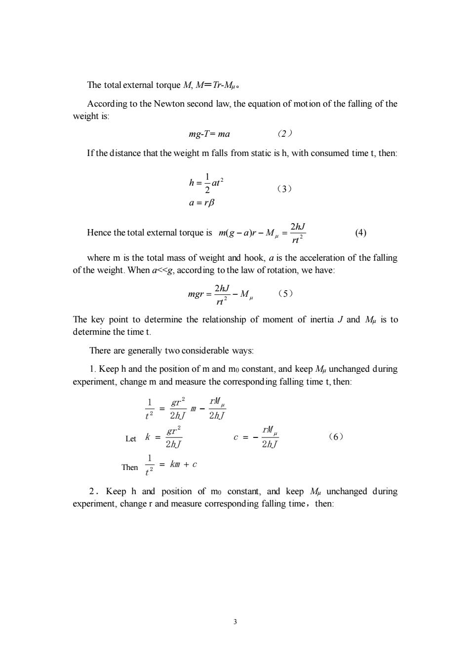
O Figure 1 Inertia experimental apparatus of rigid body The inertia experimental apparatus of rigid body is shown in Figure 1.Cone pulley A is a rotating object with five different radius(15、25、30、20、l0mm),with homogeneous thin rods B and B'with evenly divided scale at its two sides.Two movable cylindrical weights mo are located at B and B',respectively.They form together a rigid body system that can rotate around fixed axis OO'.There is a thin wire connected with the weight m.Different number of weights can be placed on the hook to change the torque applied on the rotating system. Principle: When a rigid body rotates around a fixed axis,according to the law of rotation, there is: M=JB (1) In which M is the total external torque being exerted on the rigid body,J is the moment of inertia of the rigid body to this axis,B is the angular acceleration In the apparatus,there are two external torques exerted on the rigid body system: One is the torque from the tension of the wire T,Mr=Tr,r is the radius of the reel on the cone pulley. Another is the friction torque at the bearings M
2 Figure 1 Inertia experimental apparatus of rigid body The inertia experimental apparatus of rigid body is shown in Figure 1. Cone pulley A is a rotating object with five different radius (15、25、30、20、10mm), with homogeneous thin rods B and B′ with evenly divided scale at its two sides. Two movable cylindrical weights m0 are located at B and B′, respectively. They form together a rigid body system that can rotate around fixed axis OO′. There is a thin wire connected with the weight m. Different number of weights can be placed on the hook to change the torque applied on the rotating system. Principle: When a rigid body rotates around a fixed axis,according to the law of rotation, there is: M = J (1) In which M is the total external torque being exerted on the rigid body, J is the moment of inertia of the rigid body to this axis, β is the angular acceleration In the apparatus, there are two external torques exerted on the rigid body system: One is the torque from the tension of the wire T, MT=T r, r is the radius of the reel on the cone pulley. Another is the friction torque at the bearings Mμ. A B B′ m0 m0 m O′ O

The total external torque M,M=Tr-M According to the Newton second law,the equation of motion of the falling of the weight is: mg-T=ma (2) If the distance that the weight m falls from static is h,with consumed time t,then: h=Lat 2 (3) a=rB Hence the total extemal torque ism(gM (4) where m is the total mass of weight and hook,a is the acceleration of the falling of the weight.When a<<g,according to the law of rotation,we have: mgr 2hJ-M (5) 112 The key point to determine the relationship of moment of inertiaJ and M is to determine the time t. There are generally two considerable ways: 1.Keep h and the position of m and mo constant,and keep M unchanged during experiment,change m and measure the correspond ing falling time t,then: 1。gr2mM =2hm- 2hJ Lt本sr C=- (6) h/ 2h/ 1 Thcn京=k+c 2.Keep h and position of mo constant,and keep M unchanged during experiment,change r and measure corresponding falling time,then:
3 The total external torque M, M=Tr-Mμ。 According to the Newton second law, the equation of motion of the falling of the weight is: mg-T= ma (2) If the distance that the weight m falls from static is h, with consumed time t, then: a r h at = = 2 2 1 (3) Hence the total external torque is 2 2 ( ) rt hJ m g − a r − M = (4) where m is the total mass of weight and hook, a is the acceleration of the falling of the weight. When a<<g, according to the law of rotation, we have: M rt hJ mgr = − 2 2 (5) The key point to determine the relationship of moment of inertia J and Mμ is to determine the time t. There are generally two considerable ways: 1. Keep h and the position of m and m0 constant, and keep Mμ unchanged during experiment, change m and measure the corresponding falling time t, then: km c t hJ rM c hJ gr k hJ rM m hJ gr t = + = = − = − 2 2 2 2 1 2 2 2 2 1 (6) 2.Keep h and position of m0 constant, and keep Mμ unchanged during experiment, change r and measure corresponding falling time,then: Let Then

1 mg 2hJ 2hJ Let k'=8m c=- (7) 2hJ 2hJ Then m=kr+tc 1 If the rotating axis pass through the mass center of the object,with corresponding moment of inertia marked withJo,and suppose another axis is parallel to this axis,with distance d,with corresponding moment of inertia around this axis marked with.J.Then J and Jo satisfy: J=Jo+md2 (8) Where m is the mass of the rotating system.The above equation is the parallel axis theorem. Content: 1.Adjust the experimental setup: Remove the cone pulley,mount the alignment pin,adjust the feet of the setup and adjust it vertical. Install the cone pulley,adjust the screw G to make it move freely to keep the friction torque unchanged during the experiment. 2.Measure the moment of inertia of the system around the center axis. (1)Set =(e.g.=2.5cm),place mo at certain position(e.g5,5),let the weight fall from rest at a fixed height. Change the weight m(increment is 5.00g each time),measure the falling time t,take average of three times.Draw the graph and obtain k and c.Calculate J and M (2)Fix the position of mo and keep m=20.00g,change r,repeat the above steps for different r,again take average of three times.Draw the graph and obtain k'and c. Calculate J and Mu. 3.Test the relationship of moment of inertia with the mass. (1)Keep the other conditions (h,r,etc.)constant,exchange mo with aluminum heavy weight mo',place it at the same position (e.g.,5,5'),repeat above steps and make a list.Calculate J and Mu
4 ' ' 2 ' ' 2 1 2 2 2 2 1 k r c rt hJ M c hJ gm k hJ M r hJ mg rt = + = = − = − (7) * If the rotating axis pass through the mass center of the object, with corresponding moment of inertia marked with J0, and suppose another axis is parallel to this axis, with distance d, with corresponding moment of inertia around this axis marked with J. Then J and J0 satisfy: J= J0+md2 (8) Where m is the mass of the rotating system. The above equation is the parallel axis theorem. Content: 1.Adjust the experimental setup: Remove the cone pulley, mount the alignment pin, adjust the feet of the setup and adjust it vertical. Install the cone pulley, adjust the screw G to make it move freely to keep the friction torque unchanged during the experiment. 2.Measure the moment of inertia of the system around the center axis. (1)Set r=r1 (e.g., r1=2.5cm), place m0 at certain position (e.g., 5, 5′), let the weight fall from rest at a fixed height. Change the weight m (increment is 5.00g each time), measure the falling time t, take average of three times. Draw the graph and obtain k and c. Calculate J and Mμ (2)Fix the position of m0 and keep m=20.00g, change r, repeat the above steps for different r, again take average of three times. Draw the graph and obtain k’ and c. Calculate J and Mμ. 3.Test the relationship of moment of inertia with the mass. (1)Keep the other conditions (h, r, etc.) constant, exchange m0 with aluminum heavy weight m0′, place it at the same position (e.g., 5, 5′), repeat above steps and make a list. Calculate J and Mμ. Let Then

(2)Compare these results with those from the content 2(1)and analyze it. 4.Test the relationship of moment of inertia with the mass distribution. (1)Keep the other conditions(h,r,etc.)constant,change the position of the heavy weight mo,repeat the steps in content 2(1),make a list.Calculate J and Mu (2)Compare these results with those from the content 2(1)and analyze it. Discussion: 1.What will the changing of r indicate?Does it influenceJ? 2.What experimental conditions should be satisfied prior to this experiment? How? 3.Analyze negative factors on this experiment.How to reduce them? 5
5 (2)Compare these results with those from the content 2(1) and analyze it. 4.Test the relationship of moment of inertia with the mass distribution. (1)Keep the other conditions (h, r, etc.) constant, change the position of the heavy weight m0, repeat the steps in content 2(1), make a list. Calculate J and Mμ. (2)Compare these results with those from the content 2(1) and analyze it. Discussion: 1.What will the changing of r indicate? Does it influence J? 2.What experimental conditions should be satisfied prior to this experiment? How? 3. Analyze negative factors on this experiment. How to reduce them?