Exp.6 Studies of Antenna Introductions Antenna is a device which can effectively transmit or receive electromagnetic waves.There have many different types of antennas for different applications.One important parameter describing the antenna electrical properties is directivity.For different application,the directivity may different.The directivity of the antenna is generally refers to the angular dependence when the antenna transmits or receives EM radiation energy.In principle,one can have the answer by solving the Maxwell's equations with corresponding boundary condition.However,this is a much more complex than it looks like.You may refer monographs for details.Here we only study the directivity of antenna through experiments. Different Types of Antenna 1.Dipole Antenna: This kind of antennas is composed of two identical straight wires.Its radius is a,and the length is /This antenna is widely used in various wireless communication devices. Ignoring the radiation-induced attenuation effect and the transducer thickness effect,the normalized direction function can be expressed as: f(0)=cos(BIcos0)-cos(B) f()mx sin 0 Where B=2/A is phase coefficient.The figures following are the functions for different I Fig.1 I/A=0.25 Directivity Function Fig.2 /A=0.5 Directivity Function 101 840- 1 85- 17 1 20 Fig.3 I/A=0.75Dirctivity Function Fig.4 I/A=1 Directivity Function
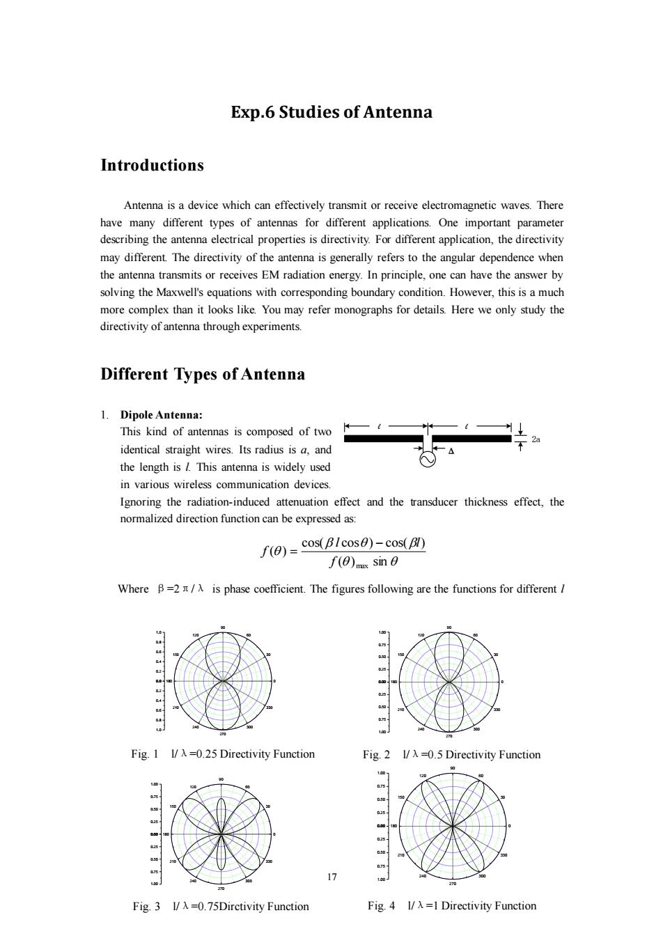
17 Exp.6 Studies of Antenna Introductions Antenna is a device which can effectively transmit or receive electromagnetic waves. There have many different types of antennas for different applications. One important parameter describing the antenna electrical properties is directivity. For different application, the directivity may different. The directivity of the antenna is generally refers to the angular dependence when the antenna transmits or receives EM radiation energy. In principle, one can have the answer by solving the Maxwell's equations with corresponding boundary condition. However, this is a much more complex than it looks like. You may refer monographs for details. Here we only study the directivity of antenna through experiments. Different Types of Antenna 1. Dipole Antenna: This kind of antennas is composed of two identical straight wires. Its radius is a, and the length is l. This antenna is widely used in various wireless communication devices. Ignoring the radiation-induced attenuation effect and the transducer thickness effect, the normalized direction function can be expressed as: ( ) sin cos( cos ) cos( ) ( ) max f l l f − = Where β=2π/λ is phase coefficient. The figures following are the functions for different l l l Δ 2a 0.0 0.2 0.4 0.6 0.8 1.0 0 30 60 90 120 150 180 210 240 270 300 330 0.0 0.2 0.4 0.6 0.8 1.0 Fig. 1 l/λ=0.25 Directivity Function 0.00 0.25 0.50 0.75 1.00 0 30 60 90 120 150 180 210 240 270 300 330 0.00 0.25 0.50 0.75 1.00 Fig. 2 l/λ=0.5 Directivity Function 0.00 0.25 0.50 0.75 1.00 0 30 60 90 120 150 180 210 240 270 300 330 0.00 0.25 0.50 0.75 1.00 Fig. 4 l/λ=1 Directivity Function 0.00 0.25 0.50 0.75 1.00 0 30 60 90 120 150 180 210 240 270 300 330 0.00 0.25 0.50 0.75 1.00 Fig. 3 l/λ=0.75Dirctivity Function

andλ. The 0 degree shown in the figure is perpendicular to the dipole.Note that at 0 degree direction,the energy received by the antenna is 0.This is easy to be understood,since the position there is in the same or symmetrical wavefront,and therefore no current can be induced.According to the antenna's reciprocal law,the directivities of one antenna are the same for transmitting and receiving.In normal applications,the ratio is often taken as 21/)= 0.5 or 1,where the IsT one is called a half-wave dipole antenna,and the 2nd one full-wave dipole antenna. 2.Reflector Antennas: When put several metal sticks around the emitter,the symmetry is broken.These metal sticks are called directors and reflectors.Their sizes and positions determine the properties of the antenna.This kind of TV antenna can be found on top of many buildings.In this experiment, different reflector antennas will be used,and their directivity will be measured. 3.HelicalAntennas: Helix Antenna is composed of a metal wire.It can be seen as a deformed coaxial cable.In range0.25λ≤D≤ 0.45 A,its directivity reaches peak value,known as axial mode radiation states.This is commonly used working M1 state.The left-handed helical antenna receives left-handed polarize waves,and so does the right-handed one. Instruments and Procedure Emitter:It is composed of GUNN oscillator,horn antenna,and power supply.Power supply provides f=1KHz pulser,The frequency of GUNN oscillator is f=9.40 GHz,ie. MOD GUNN OSO microwave of wavelength=32mm.The horn antenna couples the microwave to free space, and transform to be plane wave.It is polarized.(How to confirm this?) Receiver:It is composed of the antenna to be tested,amplifier,Rotating platform,antenna bracket,and power supply.The received microwave signal is modulated by the Schottky diode detector to be 1KHz square wave signal.This signal is then amplified by the amplifier.And then be monitored by AC voltmeter. Antenna to be tested: 1.Symmetrical Antenna:Mount the short metal sticks with caution.Measure the directivity functions of the antenna.Ensure that you write down all parameters for data analysis. 2.Helical Antenna:Check the chirality of the antenna.Measure the directivity functions of the antenna.Compare the results.Can you predict the results before your measurement? Cautions:Keep the emitter and receiver at the same position during your measurement.Try to keep the same ambient state,so that you can compare the results from different antenna. 伊
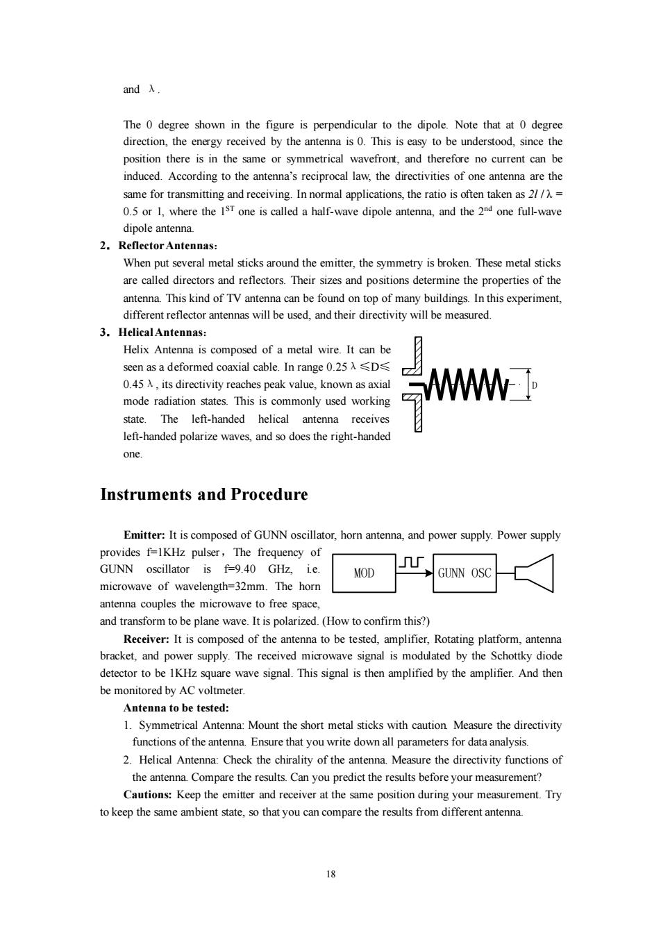
18 and λ. The 0 degree shown in the figure is perpendicular to the dipole. Note that at 0 degree direction, the energy received by the antenna is 0. This is easy to be understood, since the position there is in the same or symmetrical wavefront, and therefore no current can be induced. According to the antenna’s reciprocal law, the directivities of one antenna are the same for transmitting and receiving. In normal applications, the ratio is often taken as 2l / λ = 0.5 or 1, where the 1 ST one is called a half-wave dipole antenna, and the 2 nd one full-wave dipole antenna. 2.Reflector Antennas: When put several metal sticks around the emitter, the symmetry is broken. These metal sticks are called directors and reflectors. Their sizes and positions determine the properties of the antenna. This kind of TV antenna can be found on top of many buildings. In this experiment, different reflector antennas will be used, and their directivity will be measured. 3.Helical Antennas: Helix Antenna is composed of a metal wire. It can be seen as a deformed coaxial cable. In range 0.25λ≤D≤ 0.45λ, its directivity reaches peak value, known as axial mode radiation states. This is commonly used working state. The left-handed helical antenna receives left-handed polarize waves, and so does the right-handed one. Instruments and Procedure Emitter: It is composed of GUNN oscillator, horn antenna, and power supply. Power supply provides f=1KHz pulser,The frequency of GUNN oscillator is f=9.40 GHz, i.e. microwave of wavelength=32mm. The horn antenna couples the microwave to free space, and transform to be plane wave. It is polarized. (How to confirm this?) Receiver: It is composed of the antenna to be tested, amplifier, Rotating platform, antenna bracket, and power supply. The received microwave signal is modulated by the Schottky diode detector to be 1KHz square wave signal. This signal is then amplified by the amplifier. And then be monitored by AC voltmeter. Antenna to be tested: 1. Symmetrical Antenna: Mount the short metal sticks with caution. Measure the directivity functions of the antenna. Ensure that you write down all parameters for data analysis. 2. Helical Antenna: Check the chirality of the antenna. Measure the directivity functions of the antenna. Compare the results. Can you predict the results before your measurement? Cautions: Keep the emitter and receiver at the same position during your measurement. Try to keep the same ambient state, so that you can compare the results from different antenna. D MOD GUNN OSC

Data Analysis: 1.Draw normalized directivity functions by using polar coordinates,and label the maximum direction and values on the drawing.Compare the difference. 2.(Optional)Try to make a simple part,and attach it to the antenna,to see what happens. 0
19 Data Analysis: 1.Draw normalized directivity functions by using polar coordinates, and label the maximum direction and values on the drawing. Compare the difference. 2.(Optional) Try to make a simple part, and attach it to the antenna, to see what happens