正在加载图片...

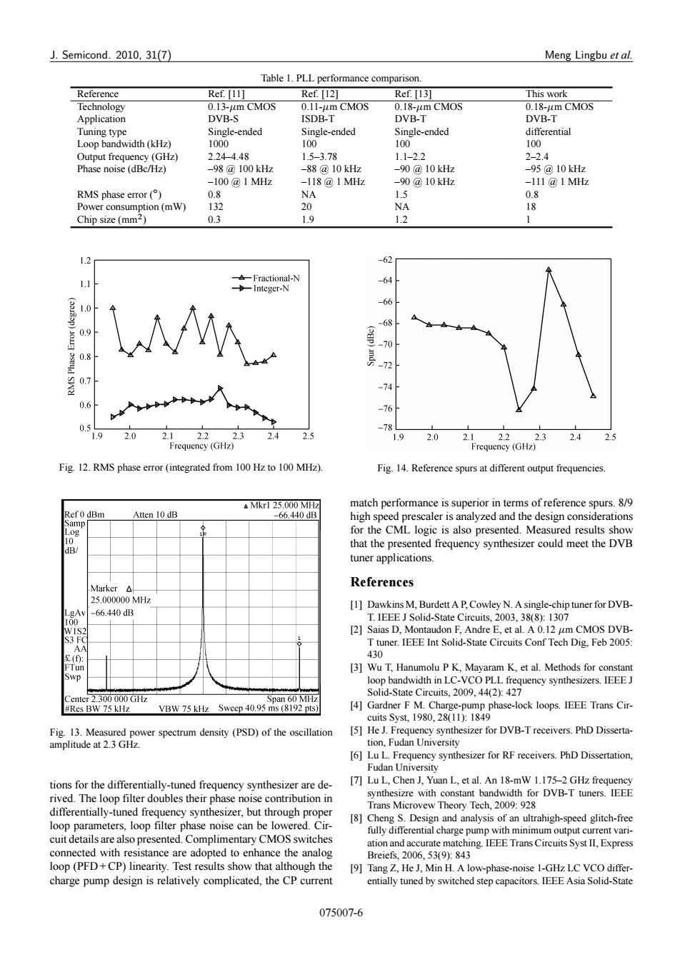
J.Semicond.2010,31(7) Meng Lingbu et al. Table 1.PLL performance comparison. Reference Ref.[11] Ref.[12] Ref.[13] This work Technology 0.13-um CMOS 0.11-um CMOS 0.18-um CMOS 0.18-um CMOS Application DVB-S ISDB-T DVB-T DVB-T Tuning type Single-ended Single-ended Single-ended differential Loop bandwidth (kHz) 1000 100 100 100 Output frequency (GHz) 2.24-4.48 1.5-3.78 1.1-2.2 2-2.4 Phase noise (dBc/Hz) -98@100kHz -88@10kHz -90@10kHz -95@10kHz -100@1MHz -118@1MHz -90@10kHz -111@1MHz RMS phase error(°) 0.8 NA 1.5 0.8 Power consumption(mW) 132 20 NA 18 Chip size (mm2) 0.3 1.9 1.2 1 -62 A-Fractional-N -64 Integer-N 3 -66 1.0 ap) -68 09 0.8 12 -74 0.6 -76 -78 1.9 2.0 2.1 2.2 2.3 2.4 2.5 1.9 2.0 2.12.2 2.3 2.4 2.5 Frequency (GHz) Frequency(GHz) Fig.12.RMS phase error (integrated from 100 Hz to 100 MHz). Fig.14.Reference spurs at different output frequencies. Mkr1 25.000 MHz match performance is superior in terms of reference spurs.8/9 Ref0 dBm Atten 10 dB -66.440dB high speed prescaler is analyzed and the design considerations Samp Log for the CML logic is also presented.Measured results show 1 dB/ that the presented frequency synthesizer could meet the DVB tuner applications. Marker△ References 25.000000MHz [1]Dawkins M,Burdett A P,Cowley N.A single-chip tuner for DVB- gAv -66.440dB 100 T.IEEE J Solid-State Circuits,2003,38(8):1307 WIS2 [2]Saias D,Montaudon F,Andre E,et al.A 0.12 um CMOS DVB- S3 FC T tuner.IEEE Int Solid-State Circuits Conf Tech Dig,Feb 2005: AA s(①: 430 FTun [3]Wu T,Hanumolu P K,Mayaram K,et al.Methods for constant loop bandwidth in LC-VCO PLL frequency synthesizers.IEEE J Solid-State Circuits,2009.44(2):427 Center 2.300 000 GHz Span 60 MHz #Res BW 75 kHz VBW 75 kHz Sweep 40.95 ms (8192 pts) [4]Gardner F M.Charge-pump phase-lock loops.IEEE Trans Cir- cuits Syst.1980,28(11:1849 Fig.13.Measured power spectrum density (PSD)of the oscillation [5]He J.Frequency synthesizer for DVB-T receivers.PhD Disserta- amplitude at 2.3 GHz tion,Fudan University [6]Lu L.Frequency synthesizer for RF receivers.PhD Dissertation, Fudan University tions for the differentially-tuned frequency synthesizer are de- [7]Lu L,Chen J,Yuan L,et al.An 18-mW 1.175-2 GHz frequency rived.The loop filter doubles their phase noise contribution in synthesizre with constant bandwidth for DVB-T tuners.IEEE Trans Microvew Theory Tech,2009:928 differentially-tuned frequency synthesizer,but through proper [8]Cheng S.Design and analysis of an ultrahigh-speed glitch-free loop parameters,loop filter phase noise can be lowered.Cir- fully differential charge pump with minimum output current vari- cuit details are also presented.Complimentary CMOS switches ation and accurate matching.IEEE Trans Circuits Syst II,Express connected with resistance are adopted to enhance the analog Breiefs,2006,53(9):843 loop(PFD+CP)linearity.Test results show that although the [9]Tang Z,He J,Min H.A low-phase-noise 1-GHz LC VCO differ- charge pump design is relatively complicated,the CP current entially tuned by switched step capacitors.IEEE Asia Solid-State 075007-6J. Semicond. 2010, 31(7) Meng Lingbu et al. Table 1. PLL performance comparison. Reference Ref. [11] Ref. [12] Ref. [13] This work Technology 0.13-m CMOS 0.11-m CMOS 0.18-m CMOS 0.18-m CMOS Application DVB-S ISDB-T DVB-T DVB-T Tuning type Single-ended Single-ended Single-ended differential Loop bandwidth (kHz) 1000 100 100 100 Output frequency (GHz) 2.24–4.48 1.5–3.78 1.1–2.2 2–2.4 Phase noise (dBc/Hz) –98 @ 100 kHz –100 @ 1 MHz –88 @ 10 kHz –118 @ 1 MHz –90 @ 10 kHz –90 @ 10 kHz –95 @ 10 kHz –111 @ 1 MHz RMS phase error (ı / 0.8 NA 1.5 0.8 Power consumption (mW) 132 20 NA 18 Chip size (mm2 / 0.3 1.9 1.2 1 Fig. 12. RMS phase error (integrated from 100 Hz to 100 MHz). Fig. 13. Measured power spectrum density (PSD) of the oscillation amplitude at 2.3 GHz. tions for the differentially-tuned frequency synthesizer are derived. The loop filter doubles their phase noise contribution in differentially-tuned frequency synthesizer, but through proper loop parameters, loop filter phase noise can be lowered. Circuit details are also presented. Complimentary CMOS switches connected with resistance are adopted to enhance the analog loop (PFD + CP) linearity. Test results show that although the charge pump design is relatively complicated, the CP current Fig. 14. Reference spurs at different output frequencies. match performance is superior in terms of reference spurs. 8/9 high speed prescaler is analyzed and the design considerations for the CML logic is also presented. Measured results show that the presented frequency synthesizer could meet the DVB tuner applications. References [1] Dawkins M, Burdett A P, Cowley N. A single-chip tuner for DVBT. IEEE J Solid-State Circuits, 2003, 38(8): 1307 [2] Saias D, Montaudon F, Andre E, et al. A 0.12 m CMOS DVBT tuner. IEEE Int Solid-State Circuits Conf Tech Dig, Feb 2005: 430 [3] Wu T, Hanumolu P K, Mayaram K, et al. Methods for constant loop bandwidth in LC-VCO PLL frequency synthesizers. IEEE J Solid-State Circuits, 2009, 44(2): 427 [4] Gardner F M. Charge-pump phase-lock loops. IEEE Trans Circuits Syst, 1980, 28(11): 1849 [5] He J. Frequency synthesizer for DVB-T receivers. PhD Dissertation, Fudan University [6] Lu L. Frequency synthesizer for RF receivers. PhD Dissertation, Fudan University [7] Lu L, Chen J, Yuan L, et al. An 18-mW 1.175–2 GHz frequency synthesizre with constant bandwidth for DVB-T tuners. IEEE Trans Microvew Theory Tech, 2009: 928 [8] Cheng S. Design and analysis of an ultrahigh-speed glitch-free fully differential charge pump with minimum output current variation and accurate matching. IEEE Trans Circuits Syst II, Express Breiefs, 2006, 53(9): 843 [9] Tang Z, He J, Min H. A low-phase-noise 1-GHz LC VCO differentially tuned by switched step capacitors. IEEE Asia Solid-State 075007-6