正在加载图片...
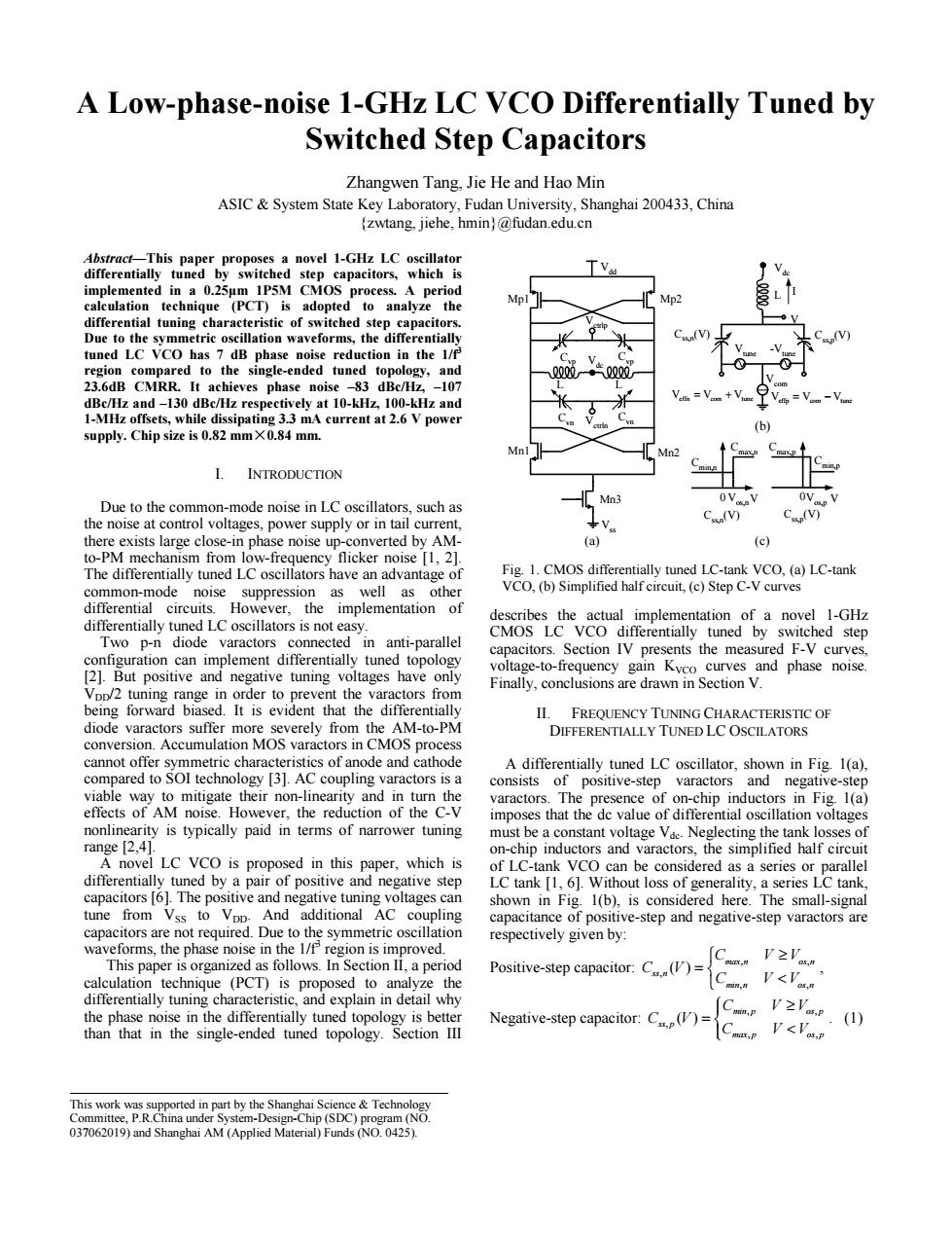
A Low-phase-noise 1-GHz LC VCO Differentially Tuned by Switched Step Capacitors Zhangwen Tang,Jie He and Hao Min ASIC System State Key Laboratory,Fudan University,Shanghai 200433,China (zwtang,jiehe,hmin)@fudan.edu.cn Abstract-This paper proposes a novel 1-GHz LC oscillator differentially tuned by switched step capacitors,which is implemented in a 0.25um 1P5M CMOS process.A period Mp calculation technique (PCT)is adopted to analyze the Mp2 differential tuning characteristic of switched step capacitors. Due to the symmetric oscillation waveforms,the differentially tuned LC VCO has 7 dB phase noise reduction in the 1/f region compared to the single-ended tuned topology,and 23.6dB CMRR.It achieves phase noise -83 dBc/Hz,-107 dBc/Hz and-130 dBc/Hz respectively at 10-kHz,100-kHz and 1-MHz offsets,while dissipating 3.3 mA current at 2.6 V power C supply.Chip size is 0.82 mm X0.84 mm. Mn I.INTRODUCTION Due to the common-mode noise in LC oscillators,such as the noise at control voltages,power supply or in tail current, (V) C(V) there exists large close-in phase noise up-converted by AM- (a) (c) to-PM mechanism from low-frequency flicker noise [1,2]. The differentially tuned LC oscillators have an advantage of Fig.1.CMOS differentially tuned LC-tank VCO,(a)LC-tank common-mode noise suppression as well as other VCO,(b)Simplified half circuit,(c)Step C-V curves differential circuits.However.the implementation of describes the actual implementation of a novel 1-GHz differentially tuned LC oscillators is not easy. CMOS LC VCO differentially tuned by switched step Two p-n diode varactors connected in anti-parallel configuration can implement differentially tuned topology capacitors.Section IV presents the measured F-V curves, [2].But positive and negative tuning voltages have only voltage-to-frequency gain Kvco curves and phase noise. Finally,conclusions are drawn in Section V. Vpp/2 tuning range in order to prevent the varactors from being forward biased.It is evident that the differentially II.FREQUENCY TUNING CHARACTERISTIC OF diode varactors suffer more severely from the AM-to-PM DIFFERENTIALLY TUNED LC OSCILATORS conversion.Accumulation MOS varactors in CMOS process cannot offer symmetric characteristics of anode and cathode A differentially tuned LC oscillator,shown in Fig.1(a), compared to SOI technology [3].AC coupling varactors is a consists of positive-step varactors and negative-step viable way to mitigate their non-linearity and in turn the varactors.The presence of on-chip inductors in Fig.1(a) effects of AM noise.However,the reduction of the C-V imposes that the dc value of differential oscillation voltages nonlinearity is typically paid in terms of narrower tuning must be a constant voltage Vac.Neglecting the tank losses of range [2,4]. on-chip inductors and varactors,the simplified half circuit A novel LC VCO is proposed in this paper,which is of LC-tank VCO can be considered as a series or parallel differentially tuned by a pair of positive and negative step LC tank [1,6].Without loss of generality,a series LC tank, capacitors [6].The positive and negative tuning voltages can shown in Fig.1(b),is considered here.The small-signal tune from Vss to VDD.And additional Ac coupling capacitance of positive-step and negative-step varactors are capacitors are not required.Due to the symmetric oscillation respectively given by: waveforms,the phase noise in the 1/f region is improved. This paper is organized as follows.In Section II,a period V≥Vsm Positive-step capacitor:CV)= calculation technique (PCT)is proposed to analyze the differentially tuning characteristic,and explain in detail why the phase noise in the differentially tuned topology is better than that in the single-ended tuned topology.Section III Neative-stp.C()C (1) This work was supported in part by the Shanghai Science Technology Committee,P.R.China under System-Design-Chip(SDC)program(NO 037062019)and Shanghai AM (Applied Material)Funds (NO.0425).A Low-phase-noise 1-GHz LC VCO Differentially Tuned by Switched Step Capacitors Zhangwen Tang, Jie He and Hao Min ASIC & System State Key Laboratory, Fudan University, Shanghai 200433, China {zwtang, jiehe, hmin}@fudan.edu.cn Abstract—This paper proposes a novel 1-GHz LC oscillator differentially tuned by switched step capacitors, which is implemented in a 0.25µm 1P5M CMOS process. A period calculation technique (PCT) is adopted to analyze the differential tuning characteristic of switched step capacitors. Due to the symmetric oscillation waveforms, the differentially tuned LC VCO has 7 dB phase noise reduction in the 1/f3 region compared to the single-ended tuned topology, and 23.6dB CMRR. It achieves phase noise –83 dBc/Hz, –107 dBc/Hz and –130 dBc/Hz respectively at 10-kHz, 100-kHz and 1-MHz offsets, while dissipating 3.3 mA current at 2.6 V power supply. Chip size is 0.82 mm×0.84 mm. I. INTRODUCTION Due to the common-mode noise in LC oscillators, such as the noise at control voltages, power supply or in tail current, there exists large close-in phase noise up-converted by AMto-PM mechanism from low-frequency flicker noise [1, 2]. The differentially tuned LC oscillators have an advantage of common-mode noise suppression as well as other differential circuits. However, the implementation of differentially tuned LC oscillators is not easy. Two p-n diode varactors connected in anti-parallel configuration can implement differentially tuned topology [2]. But positive and negative tuning voltages have only VDD/2 tuning range in order to prevent the varactors from being forward biased. It is evident that the differentially diode varactors suffer more severely from the AM-to-PM conversion. Accumulation MOS varactors in CMOS process cannot offer symmetric characteristics of anode and cathode compared to SOI technology [3]. AC coupling varactors is a viable way to mitigate their non-linearity and in turn the effects of AM noise. However, the reduction of the C-V nonlinearity is typically paid in terms of narrower tuning range [2,4]. A novel LC VCO is proposed in this paper, which is differentially tuned by a pair of positive and negative step capacitors [6]. The positive and negative tuning voltages can tune from VSS to VDD. And additional AC coupling capacitors are not required. Due to the symmetric oscillation waveforms, the phase noise in the 1/f3 region is improved. This paper is organized as follows. In Section II, a period calculation technique (PCT) is proposed to analyze the differentially tuning characteristic, and explain in detail why the phase noise in the differentially tuned topology is better than that in the single-ended tuned topology. Section III describes the actual implementation of a novel 1-GHz CMOS LC VCO differentially tuned by switched step capacitors. Section IV presents the measured F-V curves, voltage-to-frequency gain KVCO curves and phase noise. Finally, conclusions are drawn in Section V. II. FREQUENCY TUNING CHARACTERISTIC OF DIFFERENTIALLY TUNED LC OSCILATORS A differentially tuned LC oscillator, shown in Fig. 1(a), consists of positive-step varactors and negative-step varactors. The presence of on-chip inductors in Fig. 1(a) imposes that the dc value of differential oscillation voltages must be a constant voltage Vdc. Neglecting the tank losses of on-chip inductors and varactors, the simplified half circuit of LC-tank VCO can be considered as a series or parallel LC tank [1, 6]. Without loss of generality, a series LC tank, shown in Fig. 1(b), is considered here. The small-signal capacitance of positive-step and negative-step varactors are respectively given by: Positive-step capacitor: , , , , , ( ) ≥ = < max n os n ss n min n os n C VV C V C VV , Negative-step capacitor: , , , , , ( ) ≥ = < min p os p ss p max p os p C VV C V C VV . (1) This work was supported in part by the Shanghai Science & Technology Committee, P.R.China under System-Design-Chip (SDC) program (NO. 037062019) and Shanghai AM (Applied Material) Funds (NO. 0425). L Vctrln Mn1 Mn2 Mp1 Mp2 Mn3 L Vdc L Css,p(V) Vdc Cmax,n Cmin,n Vos,nV Css,n(V) V (a) (c) Vdd Vss Vctrlp Cvp Cvp Cvn Cvn Css,n(V) Cmax,p Cmin,p Vos,p V Css,p(V) I Vcom Vtune -Vtune VVV effn com tune = + VVV effp com tune = − (b) 0 0 Fig. 1. CMOS differentially tuned LC-tank VCO, (a) LC-tank VCO, (b) Simplified half circuit, (c) Step C-V curves