正在加载图片...

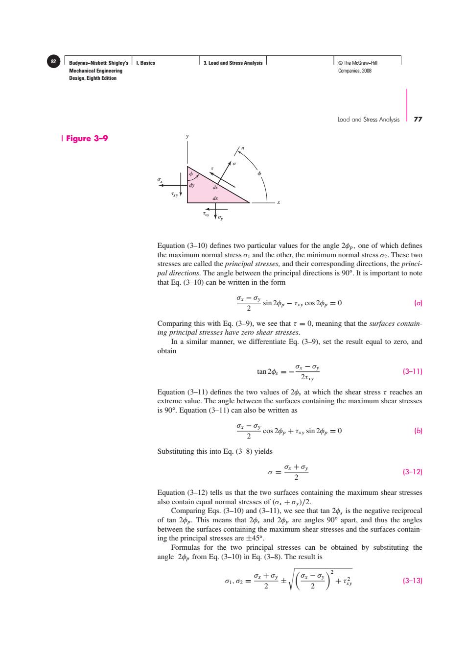
Budynas-Nisbett:Shigley's I.Basics 3.Load and Stress Analysis I©The McGraw-Hil Mechanical Engineering Companies,2008 Design,Eighth Edition Load and Stress Analysis 77 I Figure 3-9 Equation (3-10)defines two particular values for the angle 2p,one of which defines the maximum normal stress o and the other,the minimum normal stress o2.These two stresses are called the principal stresses,and their corresponding directions,the princi- pal directions.The angle between the principal directions is 90.It is important to note that Eq.(3-10)can be written in the form -sin2中p-xycos20p=0 2 (a) Comparing this with Eq.(3-9),we see that r=0,meaning that the surfaces contain- ing principal stresses have zero shear stresses. In a similar manner,we differentiate Eg.(3-9),set the result equal to zero,and obtain tan 20 =0x -dy (3-11) 2txy Equation (3-11)defines the two values of 20,at which the shear stress t reaches an extreme value.The angle between the surfaces containing the maximum shear stresses is 90.Equation (3-11)can also be written as ax -ay cos 20p+ty sin 20p=0 2 (6) Substituting this into Eq.(3-8)yields a=Ox+ay (3-12) 2 Equation(3-12)tells us that the two surfaces containing the maximum shear stresses also contain equal normal stresses of (ox +oy)/2. Comparing Eqs.(3-10)and (3-11),we see that tan 20,is the negative reciprocal of tan 2p.This means that 2,and 2p are angles 90 apart,and thus the angles between the surfaces containing the maximum shear stresses and the surfaces contain- ing the principal stresses are +45. Formulas for the two principal stresses can be obtained by substituting the angle 2p from Eq.(3-10)in Eq.(3-8).The result is 01,02= 0x+ (3-13) 2Budynas−Nisbett: Shigley’s Mechanical Engineering Design, Eighth Edition I. Basics 3. Load and Stress Analysis 82 © The McGraw−Hill Companies, 2008 Load and Stress Analysis 77 Equation (3–10) defines two particular values for the angle 2φp, one of which defines the maximum normal stress σ1 and the other, the minimum normal stress σ2. These two stresses are called the principal stresses, and their corresponding directions, the principal directions. The angle between the principal directions is 90°. It is important to note that Eq. (3–10) can be written in the form σx − σy 2 sin 2φp − τxy cos 2φp = 0 (a) Comparing this with Eq. (3–9), we see that τ = 0, meaning that the surfaces containing principal stresses have zero shear stresses. In a similar manner, we differentiate Eq. (3–9), set the result equal to zero, and obtain tan 2φs = −σx − σy 2τxy (3–11) Equation (3–11) defines the two values of 2φs at which the shear stress τ reaches an extreme value. The angle between the surfaces containing the maximum shear stresses is 90°. Equation (3–11) can also be written as σx − σy 2 cos 2φp + τxy sin 2φp = 0 (b) Substituting this into Eq. (3–8) yields σ = σx + σy 2 (3–12) Equation (3–12) tells us that the two surfaces containing the maximum shear stresses also contain equal normal stresses of (σx + σy )/2. Comparing Eqs. (3–10) and (3–11), we see that tan 2φs is the negative reciprocal of tan 2φp. This means that 2φs and 2φp are angles 90° apart, and thus the angles between the surfaces containing the maximum shear stresses and the surfaces containing the principal stresses are ±45◦. Formulas for the two principal stresses can be obtained by substituting the angle 2φp from Eq. (3–10) in Eq. (3–8). The result is σ1, σ2 = σx + σy 2 ± σx − σy 2 2 + τ 2 xy (3–13) x n y x xy dx ds dy y xy dx ds dy Figure 3–9����