正在加载图片...
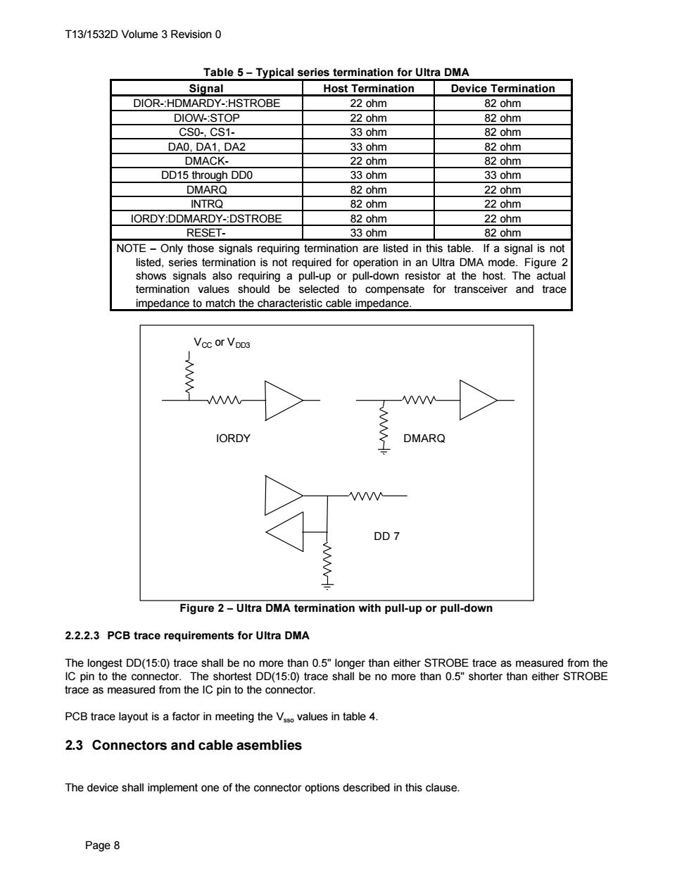
T13/1532D Volume 3 Revision 0 Table 5-Typical series termination for Ultra DMA Signal Host Termination Device Termination DIOR-:HDMARDY-:HSTROBE 22 ohm 82 ohm DIOW-:STOP 22 ohm 82 ohm CSO-,CS1- 33 ohm 82 ohm DA0.DA1.,DA2 33 ohm 82 ohm DMACK- 22 ohm 82 ohm DD15 through DDO 33 ohm 33 ohm DMARQ 82 ohm 22 ohm INTRQ 82 ohm 22 ohm IORDY:DDMARDY-:DSTROBE 82 ohm 22 ohm RESET- 33ohm 82 ohm NOTE-Only those signals requiring termination are listed in this table.If a signal is not listed,series termination is not required for operation in an Ultra DMA mode.Figure 2 shows signals also requiring a pull-up or pull-down resistor at the host.The actual termination values should be selected to compensate for transceiver and trace impedance to match the characteristic cable impedance. Vcc or VDD3 W IORDY DMARQ DD7 Figure 2-Ultra DMA termination with pull-up or pull-down 2.2.2.3 PCB trace requirements for Ultra DMA The longest DD(15:0)trace shall be no more than 0.5"longer than either STROBE trace as measured from the IC pin to the connector.The shortest DD(15:0)trace shall be no more than 0.5"shorter than either STROBE trace as measured from the IC pin to the connector. PCB trace layout is a factor in meeting the Vaso values in table 4. 2.3 Connectors and cable asemblies The device shall implement one of the connector options described in this clause. Page 8T13/1532D Volume 3 Revision 0 Page 8 Table 5 − Typical series termination for Ultra DMA Signal Host Termination Device Termination DIOR-:HDMARDY-:HSTROBE 22 ohm 82 ohm DIOW-:STOP 22 ohm 82 ohm CS0-, CS1- 33 ohm 82 ohm DA0, DA1, DA2 33 ohm 82 ohm DMACK- 22 ohm 82 ohm DD15 through DD0 33 ohm 33 ohm DMARQ 82 ohm 22 ohm INTRQ 82 ohm 22 ohm IORDY:DDMARDY-:DSTROBE 82 ohm 22 ohm RESET- 33 ohm 82 ohm NOTE − Only those signals requiring termination are listed in this table. If a signal is not listed, series termination is not required for operation in an Ultra DMA mode. Figure 2 shows signals also requiring a pull-up or pull-down resistor at the host. The actual termination values should be selected to compensate for transceiver and trace impedance to match the characteristic cable impedance. VCC or VDD3 IORDY DMARQ DD 7 Figure 2 − Ultra DMA termination with pull-up or pull-down 2.2.2.3 PCB trace requirements for Ultra DMA The longest DD(15:0) trace shall be no more than 0.5" longer than either STROBE trace as measured from the IC pin to the connector. The shortest DD(15:0) trace shall be no more than 0.5" shorter than either STROBE trace as measured from the IC pin to the connector. PCB trace layout is a factor in meeting the Vsso values in table 4. 2.3 Connectors and cable asemblies The device shall implement one of the connector options described in this clause