正在加载图片...
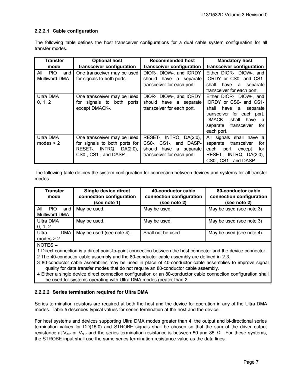
T13/1532D Volume 3 Revision 0 2.2.2.1 Cable configuration The following table defines the host transceiver configurations for a dual cable system configuration for all transfer modes. Transfer Optional host Recommended host Mandatory host mode transceiver configuration transceiver configuration transceiver configuration All PIO and One transceiver may be used DIOR-,DIOW-,and IORDY Either DIOR-,DIOW-,and Multiword DMA for signals to both ports. should have a separate IORDY or CS0-and CS1- transceiver for each port. shall have a separate transceiver for each port. Ultra DMA One transceiver may be used DIOR-,DIOW-,and IORDY Either DIOR-,DIOW-,and 0,1,2 for signals to both ports should have a separate IORDY or CS0-and CS1- except DMACK-. transceiver for each port. shall have a separate transceiver for each port. DMACK-shall have a separate transceiver for each port. Ultra DMA One transceiver may be used RESET-,INTRQ,DA(2:0). All signals shall have a modes >2 for signals to both ports for CS0-,CS1-,and DASP. separate transceiver for RESET-,INTRQ,DA(2:0), should have a separate each port except for CSO-,CS1-,and DASP-. transceiver for each port. RESET-,INTRQ,DA(2:0). CS0-,CS1-,and DASP-. The following table defines the system configuration for connection between devices and systems for all transfer modes. Transfer Single device direct 40-conductor cable 80-conductor cable mode connection configuration connection configuration connection configuration (see note 1) (see note 2) (see note 2) All PIO and May be used. May be used. May be used(see note 3) Multiword DMA Ultra DMA May be used. May be used. May be used(see note 3) 0.1,2 Ultra DMA May be used (see note 4). Shall not be used. May be used(see note 4). modes>2 NOTES- 1 Direct connection is a direct point-to-point connection between the host connector and the device connector. 2 The 40-conductor cable assembly and the 80-conductor cable assembly are defined in 2.3. 3 80-conductor cable assemblies may be used in place of 40-conductor cable assemblies to improve signal quality for data transfer modes that do not require an 80-conductor cable assembly. 4 Either a single device direct connection configuration or an 80-conductor cable connection configuration shall be used for systems operating with Ultra DMA modes greater than 2. 2.2.2.2 Series termination required for Ultra DMA Series termination resistors are required at both the host and the device for operation in any of the Ultra DMA modes.Table 5 describes typical values for series termination at the host and the device. For host systems and devices supporting Ultra DMA modes greater than 4,the output and bi-directional series termination values for DD(15:0)and STROBE signals shall be chosen so that the sum of the driver output resistance at Va2 or VoH2 and the series termination resistance is between 50 and 85 For these systems, the STROBE input shall use the same series termination resistance value as the data lines. Page 7T13/1532D Volume 3 Revision 0 Page 7 2.2.2.1 Cable configuration The following table defines the host transceiver configurations for a dual cable system configuration for all transfer modes. Transfer mode Optional host transceiver configuration Recommended host transceiver configuration Mandatory host transceiver configuration All PIO and Multiword DMA One transceiver may be used for signals to both ports. DIOR-, DIOW-, and IORDY should have a separate transceiver for each port. Either DIOR-, DIOW-, and IORDY or CS0- and CS1- shall have a separate transceiver for each port. Ultra DMA 0, 1, 2 One transceiver may be used for signals to both ports except DMACK-. DIOR-, DIOW-, and IORDY should have a separate transceiver for each port. Either DIOR-, DIOW-, and IORDY or CS0- and CS1- shall have a separate transceiver for each port. DMACK- shall have a separate transceiver for each port. Ultra DMA modes > 2 One transceiver may be used for signals to both ports for RESET-, INTRQ, DA(2:0), CS0-, CS1-, and DASP-. RESET-, INTRQ, DA(2:0), CS0-, CS1-, and DASPshould have a separate transceiver for each port. All signals shall have a separate transceiver for each port except for RESET-, INTRQ, DA(2:0), CS0-, CS1-, and DASP-. The following table defines the system configuration for connection between devices and systems for all transfer modes. Transfer mode Single device direct connection configuration (see note 1) 40-conductor cable connection configuration (see note 2) 80-conductor cable connection configuration (see note 2) All PIO and Multiword DMA May be used. May be used. May be used (see note 3) Ultra DMA 0, 1, 2 May be used. May be used. May be used (see note 3) Ultra DMA modes > 2 May be used (see note 4). Shall not be used. May be used (see note 4). NOTES – 1 Direct connection is a direct point-to-point connection between the host connector and the device connector. 2 The 40-conductor cable assembly and the 80-conductor cable assembly are defined in 2.3. 3 80-conductor cable assemblies may be used in place of 40-conductor cable assemblies to improve signal quality for data transfer modes that do not require an 80-conductor cable assembly. 4 Either a single device direct connection configuration or an 80-conductor cable connection configuration shall be used for systems operating with Ultra DMA modes greater than 2. 2.2.2.2 Series termination required for Ultra DMA Series termination resistors are required at both the host and the device for operation in any of the Ultra DMA modes. Table 5 describes typical values for series termination at the host and the device. For host systems and devices supporting Ultra DMA modes greater than 4, the output and bi-directional series termination values for DD(15:0) and STROBE signals shall be chosen so that the sum of the driver output resistance at VoL2 or VoH2 and the series termination resistance is between 50 and 85 Ω. For these systems, the STROBE input shall use the same series termination resistance value as the data lines