正在加载图片...
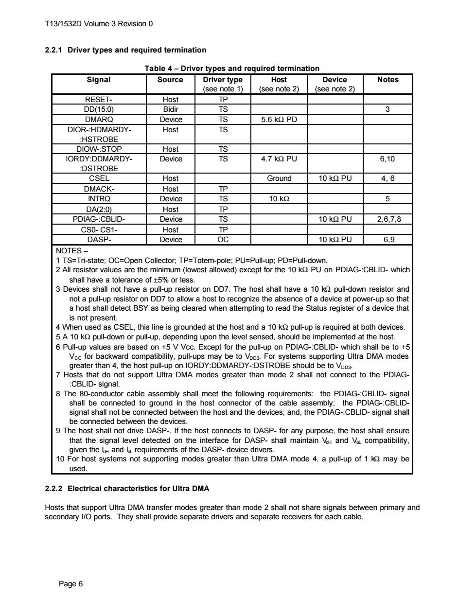
T13/1532D Volume 3 Revision 0 2.2.1 Driver types and required termination Table 4-Driver types and required termination Signal Source Driver type Host Device Notes (see note 1) (see note 2) (see note 2) RESET- Host TP DD(15:0) Bidir TS 3 DMARQ Device TS 5.6 kQ PD DIOR-:HDMARDY- Host TS :HSTROBE DIOW-:STOP Host TS IORDY:DDMARDY- Device TS 4.7 kQ PU 6,10 :DSTROBE CSEL Host Ground 10kΩPU 4,6 DMACK- Host TP INTRQ Device TS 10k2 5 DA(2:0) Host TP PDIAG-:CBLID- Device TS 10 k2 PU 26,7.8 CS0-CS1- Host TP DASP- Device OC 10 k2 PU 6,9 NOTES- 1 TS=Tri-state;OC=Open Collector;TP=Totem-pole;PU=Pull-up;PD=Pull-down. 2 All resistor values are the minimum(lowest allowed)except for the 10 k PU on PDIAG-:CBLID-which shall have a tolerance of t5%or less. 3 Devices shall not have a pull-up resistor on DD7.The host shall have a 10 k pull-down resistor and not a pull-up resistor on DD7 to allow a host to recognize the absence of a device at power-up so that a host shall detect BSY as being cleared when attempting to read the Status register of a device that is not present. 4 When used as CSEL,this line is grounded at the host and a 10 k pull-up is required at both devices. 5 A 10 k pull-down or pull-up,depending upon the level sensed,should be implemented at the host. 6 Pull-up values are based on +5 V Vcc.Except for the pull-up on PDIAG-:CBLID-which shall be to +5 Vcc for backward compatibility,pull-ups may be to VoD3.For systems supporting Ultra DMA modes greater than 4,the host pull-up on IORDY:DDMARDY-:DSTROBE should be to VoD3. 7 Hosts that do not support Ultra DMA modes greater than mode 2 shall not connect to the PDIAG- :CBLID-signal. 8 The 80-conductor cable assembly shall meet the following requirements:the PDIAG-:CBLID-signal shall be connected to ground in the host connector of the cable assembly:the PDIAG-:CBLID- signal shall not be connected between the host and the devices;and,the PDIAG-:CBLID-signal shall be connected between the devices. 9 The host shall not drive DASP-.If the host connects to DASP-for any purpose,the host shall ensure that the signal level detected on the interface for DASP-shall maintain Vh and Vo compatibility, given the l and lo requirements of the DASP-device drivers. 10 For host systems not supporting modes greater than Ultra DMA mode 4,a pull-up of 1 k may be used. 2.2.2 Electrical characteristics for Ultra DMA Hosts that support Ultra DMA transfer modes greater than mode 2 shall not share signals between primary and secondary 1/O ports.They shall provide separate drivers and separate receivers for each cable. Page 6T13/1532D Volume 3 Revision 0 Page 6 2.2.1 Driver types and required termination Table 4 − Driver types and required termination Signal Source Driver type (see note 1) Host (see note 2) Device (see note 2) Notes RESET- Host TP DD(15:0) Bidir TS 3 DMARQ Device TS 5.6 kΩ PD DIOR-:HDMARDY- :HSTROBE Host TS DIOW-:STOP Host TS IORDY:DDMARDY- :DSTROBE Device TS 4.7 kΩ PU 6,10 CSEL Host Ground 10 kΩ PU 4, 6 DMACK- Host TP INTRQ Device TS 10 kΩ 5 DA(2:0) Host TP PDIAG-:CBLID- Device TS 10 kΩ PU 2,6,7,8 CS0- CS1- Host TP DASP- Device OC 10 kΩ PU 6,9 NOTES − 1 TS=Tri-state; OC=Open Collector; TP=Totem-pole; PU=Pull-up; PD=Pull-down. 2 All resistor values are the minimum (lowest allowed) except for the 10 kΩ PU on PDIAG-:CBLID- which shall have a tolerance of ±5% or less. 3 Devices shall not have a pull-up resistor on DD7. The host shall have a 10 kΩ pull-down resistor and not a pull-up resistor on DD7 to allow a host to recognize the absence of a device at power-up so that a host shall detect BSY as being cleared when attempting to read the Status register of a device that is not present. 4 When used as CSEL, this line is grounded at the host and a 10 kΩ pull-up is required at both devices. 5 A 10 kΩ pull-down or pull-up, depending upon the level sensed, should be implemented at the host. 6 Pull-up values are based on +5 V Vcc. Except for the pull-up on PDIAG-:CBLID- which shall be to +5 VCC for backward compatibility, pull-ups may be to VDD3. For systems supporting Ultra DMA modes greater than 4, the host pull-up on IORDY:DDMARDY-:DSTROBE should be to VDD3. 7 Hosts that do not support Ultra DMA modes greater than mode 2 shall not connect to the PDIAG- :CBLID- signal. 8 The 80-conductor cable assembly shall meet the following requirements: the PDIAG-:CBLID- signal shall be connected to ground in the host connector of the cable assembly; the PDIAG-:CBLIDsignal shall not be connected between the host and the devices; and, the PDIAG-:CBLID- signal shall be connected between the devices. 9 The host shall not drive DASP-. If the host connects to DASP- for any purpose, the host shall ensure that the signal level detected on the interface for DASP- shall maintain VoH and VoL compatibility, given the IoH and IoL requirements of the DASP- device drivers. 10 For host systems not supporting modes greater than Ultra DMA mode 4, a pull-up of 1 kΩ may be used. 2.2.2 Electrical characteristics for Ultra DMA Hosts that support Ultra DMA transfer modes greater than mode 2 shall not share signals between primary and secondary I/O ports. They shall provide separate drivers and separate receivers for each cable