正在加载图片...
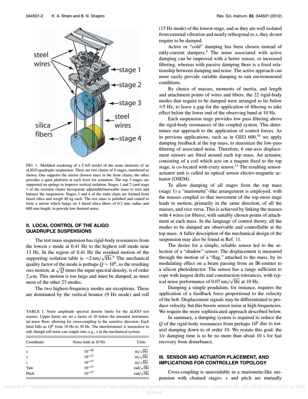
044501-2 K.A.Strain and B.N.Shapiro Rev.Sci.Instrum.83,044501(2012) (15 Hz mode)of the lowest stage,and as they are well isolated from external vibration and nearly orthogonal to x,they do not require to be damped. Active or "cold"damping has been chosen instead of steel eddy-current dampers.The noise associated with active damping can be improved with a better sensor,or increased wires filtering,whereas with passive damping there is a fixed rela- -stage 1 tionship between damping and noise.The active approach can more easily provide variable damping to suit environmental -stage 2 conditions. By choice of masses,moments of inertia,and length and attachment points of wires and fibers,the 22 rigid-body +-stage 3 modes that require to be damped were arranged to lie below 5 Hz,to leave a gap for the application of filtering to take effect below the lower end of the observing band at 10 Hz. steel Each suspension stage provides low pass filtering above silica wires the rigid-body resonances of the coupled system.This deter- fibers mines our approach to the application of control forces.As +-stage 4 in previous applications,such as in GE600,0 we apply damping feedback at the top mass,to maximize the low-pass filtering of associated noise.Therefore,6 one-axis displace- ment sensors are fitted around each top mass.An actuator, consisting of a coil which acts on a magnet fixed to the top FIG.1.Modified rendering of a CAD model of the main elements of an stage,is co-located with every sensor.The resulting sensor- aLIGO quadruple suspension.There are two chains of 4 stages,numbered as shown.One supports the mirror (lowest mass in the front chain),the other actuator unit is called an optical sensor electro-magnetic ac- provides a quiet platform at each level for actuation.The top 3 stages are tuator (OSEM). supported on springs to improve vertical isolation.Stages 1 and 2(and stage To allow damping of all stages from the top mass 3 of the reaction chain)incorporate adjustable/moveable mass to trim and balance the suspension.Stages 3 and 4 of the main chain are formed from (stage 1)a"marionette"-like arrangement is employed,with fused silica and weigh 40 kg each.The test mass is polished and coated to the masses coupled so that movement of the top-most stage form a mirror which hangs on 4 fused silica fibers of 0.2 mm radius and leads to motion,primarily in the same direction,of all the 600 mm length,to provide low thermal noise masses,and vice versa.This is achieved by linking the masses with 4 wires (or fibers).with suitably chosen points of attach- ment at each mass.In the language of control theory,all the II.LOCAL CONTROL OF THE ALIGO modes to be damped are observable and controllable at the QUADRUPLE SUSPENSIONS top mass.A fuller description of the mechanical design of the The test mass suspension has rigid-body resonances from suspension may also be found in Ref.11. the lowest x mode at 0.41 Hz to the highest roll mode near The desire for a simple,reliable sensor led to the se- 13 Hz.In the region of 0.41 Hz the residual motion of the lection of a"shadow"sensor.The displacement is measured supporting isolation table is ~2nm/VHz.8 The mechanical through the motion of a"flag,"attached to the mass,by its quality factor of the mode is perhaps ~106,so the resulting modulating effect on a beam passing from an IR-emitter to rms motion,atO times the input spectral density,is of order a silicon photodetector.The sensor has a range sufficient to 2 um.This motion is too large and must be damped.as must cope with largest drifts and construction tolerances,with typ- most of the other 23 modes. ical noise performance of 0.07 nm/Hz at 10 Hz The two highest-frequency modes are exceptions.These Damping a simple pendulum,for instance,requires the are dominated by the vertical bounce (9 Hz mode)and roll application of a feedback force proportional to the velocity of the bob.Displacement signals may be differentiated to pro- duce velocity,but this boosts sensor noise at high frequencies. TABLE I.Noise amplitude spectral density limits for the aLIGO test We require the more sophisticated approach described below. masses.Upper limits are set a factor of 10 below the intended instrumen- In summary,a damping system is required to reduce the tal noise floor.allowing for cross-coupling to the sensitive direction.Each limit falls as 1/f from 10 Hz to 30 Hz.The interferometer is insensitive to O of the rigid-body resonances from perhaps 10 due to nat- roll,though roll noise can couple into,e.g..x in the mechanical system. ural damping down to of order 10.We restate this goal:the 1/e damping time is to be no more than about 10 s for fast Coordinate Noise limit at 10 Hz Units recovery from disturbance. 10-20 m/W亚 y 1017 m/√Hz IIl.SENSOR AND ACTUATOR PLACEMENT,AND 10-17 m/VHz IMPLICATIONS FOR CONTROLLER TOPOLOGY Yaw 1017 rad/VHz Pitch 10~17 rad/W伍 Cross-coupling is unavoidable in a marionette-like sus- pension with chained stages:x and pitch are mutually Reuse of AlP Publishing content is subject to the terms at:https://publishing.aip.org/authors/nights-and-pemm ssions.Download to IP:183.195.251.6 On:Fri.22 Apr 2016 00:5549044501-2 K. A. Strain and B. N. Shapiro Rev. Sci. Instrum. 83, 044501 (2012) FIG. 1. Modified rendering of a CAD model of the main elements of an aLIGO quadruple suspension. There are two chains of 4 stages, numbered as shown. One supports the mirror (lowest mass in the front chain), the other provides a quiet platform at each level for actuation. The top 3 stages are supported on springs to improve vertical isolation. Stages 1 and 2 (and stage 3 of the reaction chain) incorporate adjustable/moveable mass to trim and balance the suspension. Stages 3 and 4 of the main chain are formed from fused silica and weigh 40 kg each. The test mass is polished and coated to form a mirror which hangs on 4 fused silica fibers of 0.2 mm radius and 600 mm length, to provide low thermal noise. II. LOCAL CONTROL OF THE ALIGO QUADRUPLE SUSPENSIONS The test mass suspension has rigid-body resonances from the lowest x mode at 0.41 Hz to the highest roll mode near 13 Hz. In the region of 0.41 Hz the residual motion of the supporting isolation table is ∼2 nm/ √Hz.8 The mechanical quality factor of the mode is perhaps Q ∼ 106, so the resulting rms motion, at √Q times the input spectral density, is of order 2μm. This motion is too large and must be damped, as must most of the other 23 modes. The two highest-frequency modes are exceptions. These are dominated by the vertical bounce (9 Hz mode) and roll TABLE I. Noise amplitude spectral density limits for the aLIGO test masses. Upper limits are set a factor of 10 below the intended instrumental noise floor, allowing for cross-coupling to the sensitive direction. Each limit falls as 1/f 2 from 10 Hz to 30 Hz. The interferometer is insensitive to roll, though roll noise can couple into, e.g., x in the mechanical system. Coordinate Noise limit at 10 Hz Units x 10−20 m/ √Hz y 10−17 m/ √Hz z 10−17 m/ √Hz Yaw 10−17 rad/ √Hz Pitch 10−17 rad/ √Hz (15 Hz mode) of the lowest stage, and as they are well isolated from external vibration and nearly orthogonal to x, they do not require to be damped. Active or “cold” damping has been chosen instead of eddy-current dampers.9 The noise associated with active damping can be improved with a better sensor, or increased filtering, whereas with passive damping there is a fixed relationship between damping and noise. The active approach can more easily provide variable damping to suit environmental conditions. By choice of masses, moments of inertia, and length and attachment points of wires and fibers, the 22 rigid-body modes that require to be damped were arranged to lie below ≈5 Hz, to leave a gap for the application of filtering to take effect below the lower end of the observing band at 10 Hz. Each suspension stage provides low pass filtering above the rigid-body resonances of the coupled system. This determines our approach to the application of control forces. As in previous applications, such as in GEO 600,10 we apply damping feedback at the top mass, to maximize the low-pass filtering of associated noise. Therefore, 6 one-axis displacement sensors are fitted around each top mass. An actuator, consisting of a coil which acts on a magnet fixed to the top stage, is co-located with every sensor.11 The resulting sensoractuator unit is called an optical sensor electro-magnetic actuator (OSEM). To allow damping of all stages from the top mass (stage 1) a “marionette”-like arrangement is employed, with the masses coupled so that movement of the top-most stage leads to motion, primarily in the same direction, of all the masses, and vice versa. This is achieved by linking the masses with 4 wires (or fibers), with suitably chosen points of attachment at each mass. In the language of control theory, all the modes to be damped are observable and controllable at the top mass. A fuller description of the mechanical design of the suspension may also be found in Ref. 11. The desire for a simple, reliable sensor led to the selection of a “shadow” sensor. The displacement is measured through the motion of a “flag,” attached to the mass, by its modulating effect on a beam passing from an IR-emitter to a silicon photodetector. The sensor has a range sufficient to cope with largest drifts and construction tolerances, with typical noise performance of 0.07 nm/ √Hz at 10 Hz. Damping a simple pendulum, for instance, requires the application of a feedback force proportional to the velocity of the bob. Displacement signals may be differentiated to produce velocity, but this boosts sensor noise at high frequencies. We require the more sophisticated approach described below. In summary, a damping system is required to reduce the Q of the rigid-body resonances from perhaps 106 due to natural damping down to of order 10. We restate this goal: the 1/e damping time is to be no more than about 10 s for fast recovery from disturbance. III. SENSOR AND ACTUATOR PLACEMENT, AND IMPLICATIONS FOR CONTROLLER TOPOLOGY Cross-coupling is unavoidable in a marionette-like suspension with chained stages: x and pitch are mutually Reuse of AIP Publishing content is subject to the terms at: https://publishing.aip.org/authors/rights-and-permissions. Download to IP: 183.195.251.6 On: Fri, 22 Apr 2016 00:55:49