正在加载图片...
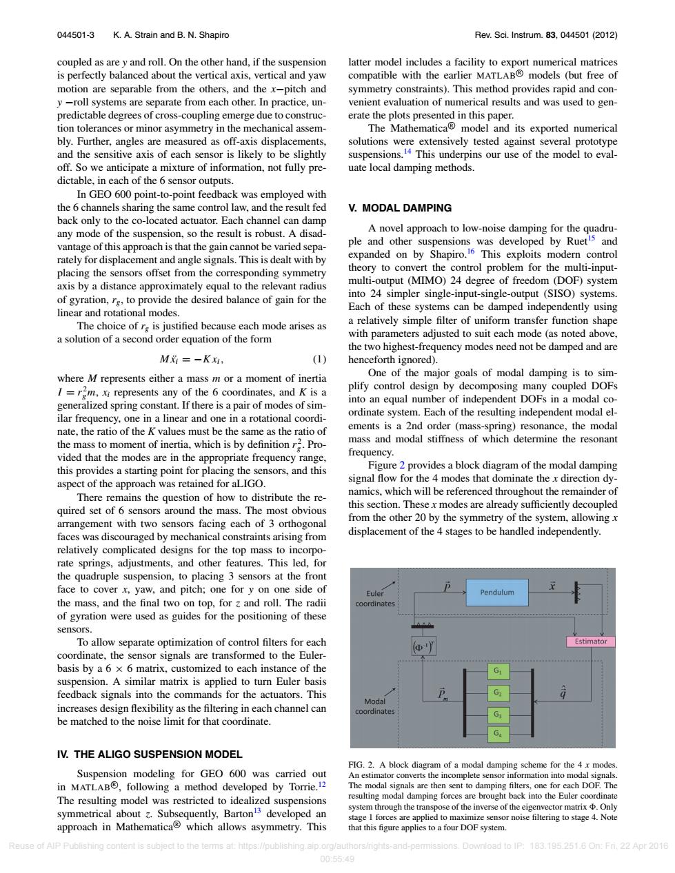
044501-3 K.A.Strain and B.N.Shapiro Rev.Sci.Instrum.83,044501(2012) coupled as are y and roll.On the other hand,if the suspension latter model includes a facility to export numerical matrices is perfectly balanced about the vertical axis,vertical and yaw compatible with the earlier MATLAB models (but free of motion are separable from the others,and the x-pitch and symmetry constraints).This method provides rapid and con- y -roll systems are separate from each other.In practice,un- venient evaluation of numerical results and was used to gen- predictable degrees of cross-coupling emerge due to construc- erate the plots presented in this paper. tion tolerances or minor asymmetry in the mechanical assem- The Mathematica model and its exported numerical bly.Further,angles are measured as off-axis displacements, solutions were extensively tested against several prototype and the sensitive axis of each sensor is likely to be slightly suspensions.14 This underpins our use of the model to eval- off.So we anticipate a mixture of information,not fully pre- uate local damping methods. dictable,in each of the 6 sensor outputs. In GEO 600 point-to-point feedback was employed with the 6 channels sharing the same control law,and the result fed V.MODAL DAMPING back only to the co-located actuator.Each channel can damp any mode of the suspension,so the result is robust.A disad- A novel approach to low-noise damping for the quadru- vantage of this approach is that the gain cannot be varied sepa- ple and other suspensions was developed by Rueti5 and rately for displacement and angle signals.This is dealt with by expanded on by Shapiro.16 This exploits modern control placing the sensors offset from the corresponding symmetry theory to convert the control problem for the multi-input- axis by a distance approximately equal to the relevant radius multi-output (MIMO)24 degree of freedom (DOF)system of gyration,rg,to provide the desired balance of gain for the into 24 simpler single-input-single-output (SISO)systems. linear and rotational modes. Each of these systems can be damped independently using The choice of rg is justified because each mode arises as a relatively simple filter of uniform transfer function shape a solution of a second order equation of the form with parameters adjusted to suit each mode (as noted above, the two highest-frequency modes need not be damped and are M=-K, (1) henceforth ignored). where M represents either a mass m or a moment of inertia One of the major goals of modal damping is to sim- plify control design by decomposing many coupled DOFs I=r2m,xi represents any of the 6 coordinates,and K is a generalized spring constant.If there is a pair of modes of sim- into an equal number of independent DOFs in a modal co- ilar frequency,one in a linear and one in a rotational coordi- ordinate system.Each of the resulting independent modal el- nate,the ratio of the K values must be the same as the ratio of ements is a 2nd order (mass-spring)resonance,the modal the mass to moment of inertia,which is by definitionr2.Pro- mass and modal stiffness of which determine the resonant vided that the modes are in the appropriate frequency range, frequency. this provides a starting point for placing the sensors,and this Figure 2 provides a block diagram of the modal damping aspect of the approach was retained for aLIGO signal flow for the 4 modes that dominate the x direction dy- namics,which will be referenced throughout the remainder of There remains the question of how to distribute the re- quired set of 6 sensors around the mass.The most obvious this section.These x modes are already sufficiently decoupled arrangement with two sensors facing each of 3 orthogonal from the other 20 by the symmetry of the system,allowingx faces was discouraged by mechanical constraints arising from displacement of the 4 stages to be handled independently. relatively complicated designs for the top mass to incorpo- rate springs,adjustments,and other features.This led,for the quadruple suspension,to placing 3 sensors at the front face to cover x,yaw,and pitch;one for y on one side of Euler Pendulum the mass,and the final two on top,for z and roll.The radii coordinates of gyration were used as guides for the positioning of these sensors. To allow separate optimization of control filters for each Estimator coordinate,the sensor signals are transformed to the Euler- basis by a 6 x 6 matrix,customized to each instance of the suspension.A similar matrix is applied to turn Euler basis feedback signals into the commands for the actuators.This G Modal increases design flexibility as the filtering in each channel can coordinates be matched to the noise limit for that coordinate. IV.THE ALIGO SUSPENSION MODEL FIG.2.A block diagram of a modal damping scheme for the 4 x modes. Suspension modeling for GEO 600 was carried out An estimator converts the incomplete sensor information into modal signals. in MATLAB,following a method developed by Torrie.12 The modal signals are then sent to damping filters,one for each DOF.The The resulting model was restricted to idealized suspensions resulting modal damping forces are brought back into the Euler coordinate symmetrical about z.Subsequently,Barton3 developed an system through the transpose of the inverse of the eigenvector matrix Only stage 1 forces are applied to maximize sensor noise filtering to stage 4.Note approach in Mathematica which allows asymmetry.This that this figure applies to a four DOF system Reuse of AlP Publishing content is subject to the terms at:https://publishing.aip.org/authors/nghts-and-permi sions. D0wmlo8doP:183.195251.60:Fi.22Apr2016 00:5549044501-3 K. A. Strain and B. N. Shapiro Rev. Sci. Instrum. 83, 044501 (2012) coupled as are y and roll. On the other hand, if the suspension is perfectly balanced about the vertical axis, vertical and yaw motion are separable from the others, and the x−pitch and y −roll systems are separate from each other. In practice, unpredictable degrees of cross-coupling emerge due to construction tolerances or minor asymmetry in the mechanical assembly. Further, angles are measured as off-axis displacements, and the sensitive axis of each sensor is likely to be slightly off. So we anticipate a mixture of information, not fully predictable, in each of the 6 sensor outputs. In GEO 600 point-to-point feedback was employed with the 6 channels sharing the same control law, and the result fed back only to the co-located actuator. Each channel can damp any mode of the suspension, so the result is robust. A disadvantage of this approach is that the gain cannot be varied separately for displacement and angle signals. This is dealt with by placing the sensors offset from the corresponding symmetry axis by a distance approximately equal to the relevant radius of gyration, rg, to provide the desired balance of gain for the linear and rotational modes. The choice of rg is justified because each mode arises as a solution of a second order equation of the form Mx¨i = −K xi, (1) where M represents either a mass m or a moment of inertia I = r 2 gm, xi represents any of the 6 coordinates, and K is a generalized spring constant. If there is a pair of modes of similar frequency, one in a linear and one in a rotational coordinate, the ratio of the K values must be the same as the ratio of the mass to moment of inertia, which is by definition r 2 g . Provided that the modes are in the appropriate frequency range, this provides a starting point for placing the sensors, and this aspect of the approach was retained for aLIGO. There remains the question of how to distribute the required set of 6 sensors around the mass. The most obvious arrangement with two sensors facing each of 3 orthogonal faces was discouraged by mechanical constraints arising from relatively complicated designs for the top mass to incorporate springs, adjustments, and other features. This led, for the quadruple suspension, to placing 3 sensors at the front face to cover x, yaw, and pitch; one for y on one side of the mass, and the final two on top, for z and roll. The radii of gyration were used as guides for the positioning of these sensors. To allow separate optimization of control filters for each coordinate, the sensor signals are transformed to the Eulerbasis by a 6 × 6 matrix, customized to each instance of the suspension. A similar matrix is applied to turn Euler basis feedback signals into the commands for the actuators. This increases design flexibility as the filtering in each channel can be matched to the noise limit for that coordinate. IV. THE ALIGO SUSPENSION MODEL Suspension modeling for GEO 600 was carried out in MATLABR , following a method developed by Torrie.12 The resulting model was restricted to idealized suspensions symmetrical about z. Subsequently, Barton13 developed an approach in MathematicaR which allows asymmetry. This latter model includes a facility to export numerical matrices compatible with the earlier MATLABR models (but free of symmetry constraints). This method provides rapid and convenient evaluation of numerical results and was used to generate the plots presented in this paper. The MathematicaR model and its exported numerical solutions were extensively tested against several prototype suspensions.14 This underpins our use of the model to evaluate local damping methods. V. MODAL DAMPING A novel approach to low-noise damping for the quadruple and other suspensions was developed by Ruet15 and expanded on by Shapiro.16 This exploits modern control theory to convert the control problem for the multi-inputmulti-output (MIMO) 24 degree of freedom (DOF) system into 24 simpler single-input-single-output (SISO) systems. Each of these systems can be damped independently using a relatively simple filter of uniform transfer function shape with parameters adjusted to suit each mode (as noted above, the two highest-frequency modes need not be damped and are henceforth ignored). One of the major goals of modal damping is to simplify control design by decomposing many coupled DOFs into an equal number of independent DOFs in a modal coordinate system. Each of the resulting independent modal elements is a 2nd order (mass-spring) resonance, the modal mass and modal stiffness of which determine the resonant frequency. Figure 2 provides a block diagram of the modal damping signal flow for the 4 modes that dominate the x direction dynamics, which will be referenced throughout the remainder of this section. These x modes are already sufficiently decoupled from the other 20 by the symmetry of the system, allowing x displacement of the 4 stages to be handled independently. FIG. 2. A block diagram of a modal damping scheme for the 4 x modes. An estimator converts the incomplete sensor information into modal signals. The modal signals are then sent to damping filters, one for each DOF. The resulting modal damping forces are brought back into the Euler coordinate system through the transpose of the inverse of the eigenvector matrix . Only stage 1 forces are applied to maximize sensor noise filtering to stage 4. Note that this figure applies to a four DOF system. Reuse of AIP Publishing content is subject to the terms at: https://publishing.aip.org/authors/rights-and-permissions. Download to IP: 183.195.251.6 On: Fri, 22 Apr 2016 00:55:49�����