正在加载图片...
△d △d d x cosa d x cosa 0 60 120180240300360 Moving Rotation(deg.)】 direction (a)rotate along the Z axis (b)phase change during rotation A Pi d Fig.2.Measured phase of a single tag rotating along the Z axis Fig.3.AoA in static scanning Fig.4.AoA in mobile scanning III.ANGLE-PROFILE-BASED MODELING The phase difference is related to the distance difference A.Limitations of Phase-based Measurement from the tag to the antennas.When h>d,the relationship between the phase difference (A0 =0A:-0A2+n.n means The RF phase is a widely used attribute of the wireless the phase offset caused by the hardware characteristics of A signal,ranging from 0 to 2.Due to the ultra-high working and A2)and the distance difference (Ad dr.A-dr.A2 frequency (indicating short wave-length)in RFIDs and fine- grained measure resolution of phase value by COTS readers, d cos a)can be approximated as: the phase is very sensitive to the tag-antenna distance,which 2 d cos a△6 2π +n (2) gives us the potential chance to achieve accurate 3D recon- 入 struction.Suppose dis is the distance between the antenna wherencan be any integer in[-共-2,共-],its range and the tag.Since the backscatter communication of RFID is 4.When d<the value range of n is smalier than 1, is round-trip,the signal totally traverses a distance of 2dis which means n has a unique value,so a is deterministic. in each communication.Besides the distance,some hardware 2)Angle in Mobile Scanning:With respect to multiple characteristics will also distort the phase value.Hence,the antennas,the phase offsets related to their own hardware phase 6 reported by the reader can be expressed as: characteristics are different,so it is hard to determine n Hence,we prefer a mobile antenna to multiple static antennas, 2元 ×2dis+n mod 2 (1) in which case the can be canceled. For a mobile antenna,the angle-of-arrival is a little different. where A is the wavelength,n represents the phase offset caused Without the loss of generality,we redefine the AoA in a mobile by the hardware characteristics.Although the phase accurately case,as shown in Fig.4.Similarly,T is the tag position reflects the distance,we face three challenges before putting and V is its projected point on the antenna moving line, into use:1)The distort factor n is unknown;2)The phase value its perpendicular distance is h.Let the mobile antenna be repeats periodically,it is not feasible to use it directly;3)In at position A,then the included angle of line TA and the addition to dis and n,our extensive experiments show that the antenna moving direction is just the angle-of-arrival (a)for tag orientation influences the phase value 0.Fig.2 plots the the tag when the antenna is at position A. phase change as a tag rotates along the Z axis,as the phase To estimate the angle at position A,we only need the phases varies continuously over the rotation.Next,we discuss how collected at the two nearby positions (P and P2),centered to use the angle-of-arrival approach to overcome above three on the antenna (PA =AP2).Thus,the phase difference at challenges,and benefit our system design in the sequel. position P and P2 can be used to estimate a with Eg.2.By combining the angles at different antenna positions,we can B.Angle Profile derive an angle profile for a specified tag. Angle-of-Arrival (AoA)is one of the most popular RF- C.Metrics of Angle Profile based localization measurements using phase difference.The Suppose there are two tags and one antenna in the same basic idea of our approach is that by moving the antenna plane(Fig.5).The antenna moves linearly from O to A,so to scan the tags,we extract the phase differences from the it passes through T first,followed by T2.When the antenna specified tags at different time points,then we derive the passes through the tag (corresponding to point V in Fig.4), geometry angles between the tag-antenna pairs at different the angle-of-arrival (o)of that tag reaches /2,naming this positions,which is called angle profile. point as the perpendicular point.Similarly,we call the distance 1)Angle in Static Scanning:As shown in Fig.3,a tag is from the tag to the perpendicular point perpendicular distance, set at T,A1 and A2 are two antennas separated by d,M is the direction perpendicular to the antenna moving direction as the middle point of A1A2.V is the projected point of T on perpendicular direction.As Ti is on the left along the antenna the tag pair line A1A2,the perpendicular distance is h.The moving direction,its perpendicular point shows earlier than included angle between line TM and line MV is the AoA T2.Hence,the perpendicular point is the key metric for the for tag T,denoted as a.Let dr.A,and dr.A represent the tags'relative positions along the moving direction. distances between T and the antennas,the antennas collect the Besides the perpendicular point,there is the other special phases as 6A and 042 respectively.641,6A2 E0,27). point:equal angle point.The equal angle point is where the
(a) rotate along the Z axis 5RWDWLRQ
GHJ
3KDVH
UDG
(b) phase change during rotation Fig. 2. Measured phase of a single tag rotating along the Z axis ܶ ߙ ο݀ ൎ ߙ
ൈ݀ ଶܣ ଵܣ ݄ ܸ ܯ ݀ Fig. 3. AoA in static scanning ܣ ܶ ߙ ο݀ ൎ ߙ
ൈ݀ ܲଵ ܲଶ ݄ ܸ ݀ ݃݊݅ݒܯ
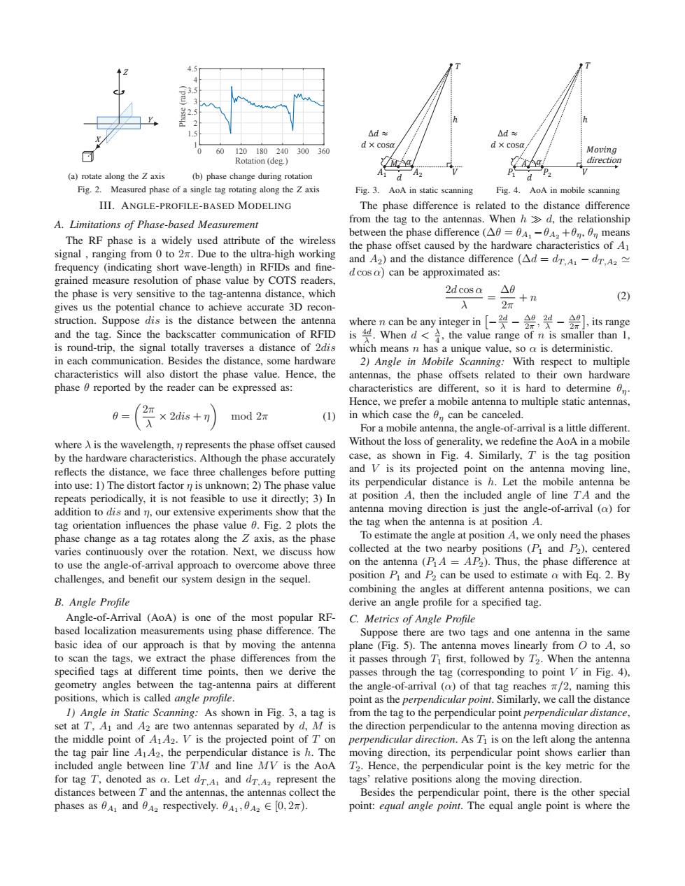
Fig. 4. AoA in mobile scanning III. ANGLE-PROFILE-BASED MODELING A. Limitations of Phase-based Measurement The RF phase is a widely used attribute of the wireless signal , ranging from 0 to 2π. Due to the ultra-high working frequency (indicating short wave-length) in RFIDs and finegrained measure resolution of phase value by COTS readers, the phase is very sensitive to the tag-antenna distance, which gives us the potential chance to achieve accurate 3D reconstruction. Suppose dis is the distance between the antenna and the tag. Since the backscatter communication of RFID is round-trip, the signal totally traverses a distance of 2dis in each communication. Besides the distance, some hardware characteristics will also distort the phase value. Hence, the phase θ reported by the reader can be expressed as: θ = 2π λ × 2dis + η mod 2π (1) where λ is the wavelength, η represents the phase offset caused by the hardware characteristics. Although the phase accurately reflects the distance, we face three challenges before putting into use: 1) The distort factor η is unknown; 2) The phase value repeats periodically, it is not feasible to use it directly; 3) In addition to dis and η, our extensive experiments show that the tag orientation influences the phase value θ. Fig. 2 plots the phase change as a tag rotates along the Z axis, as the phase varies continuously over the rotation. Next, we discuss how to use the angle-of-arrival approach to overcome above three challenges, and benefit our system design in the sequel. B. Angle Profile Angle-of-Arrival (AoA) is one of the most popular RFbased localization measurements using phase difference. The basic idea of our approach is that by moving the antenna to scan the tags, we extract the phase differences from the specified tags at different time points, then we derive the geometry angles between the tag-antenna pairs at different positions, which is called angle profile. 1) Angle in Static Scanning: As shown in Fig. 3, a tag is set at T, A1 and A2 are two antennas separated by d, M is the middle point of A1A2. V is the projected point of T on the tag pair line A1A2, the perpendicular distance is h. The included angle between line TM and line MV is the AoA for tag T, denoted as α. Let dT ,A1 and dT ,A2 represent the distances between T and the antennas, the antennas collect the phases as θA1 and θA2 respectively. θA1 , θA2 ∈ [0, 2π). The phase difference is related to the distance difference from the tag to the antennas. When h d, the relationship between the phase difference (Δθ = θA1 −θA2 +θη, θη means the phase offset caused by the hardware characteristics of A1 and A2) and the distance difference (Δd = dT ,A1 − dT ,A2 d cos α) can be approximated as: 2d cos α λ = Δθ 2π + n (2) where n can be any integer in −2d λ − Δθ 2π , 2d λ − Δθ 2π , its range is 4d λ . When d < λ 4 , the value range of n is smaller than 1, which means n has a unique value, so α is deterministic. 2) Angle in Mobile Scanning: With respect to multiple antennas, the phase offsets related to their own hardware characteristics are different, so it is hard to determine θη. Hence, we prefer a mobile antenna to multiple static antennas, in which case the θη can be canceled. For a mobile antenna, the angle-of-arrival is a little different. Without the loss of generality, we redefine the AoA in a mobile case, as shown in Fig. 4. Similarly, T is the tag position and V is its projected point on the antenna moving line, its perpendicular distance is h. Let the mobile antenna be at position A, then the included angle of line T A and the antenna moving direction is just the angle-of-arrival (α) for the tag when the antenna is at position A. To estimate the angle at position A, we only need the phases collected at the two nearby positions (P1 and P2), centered on the antenna (P1A = AP2). Thus, the phase difference at position P1 and P2 can be used to estimate α with Eq. 2. By combining the angles at different antenna positions, we can derive an angle profile for a specified tag. C. Metrics of Angle Profile Suppose there are two tags and one antenna in the same plane (Fig. 5). The antenna moves linearly from O to A, so it passes through T1 first, followed by T2. When the antenna passes through the tag (corresponding to point V in Fig. 4), the angle-of-arrival (α) of that tag reaches π/2, naming this point as the perpendicular point. Similarly, we call the distance from the tag to the perpendicular point perpendicular distance, the direction perpendicular to the antenna moving direction as perpendicular direction. As T1 is on the left along the antenna moving direction, its perpendicular point shows earlier than T2. Hence, the perpendicular point is the key metric for the tags’ relative positions along the moving direction. Besides the perpendicular point, there is the other special point: equal angle point. The equal angle point is where the�������