正在加载图片...
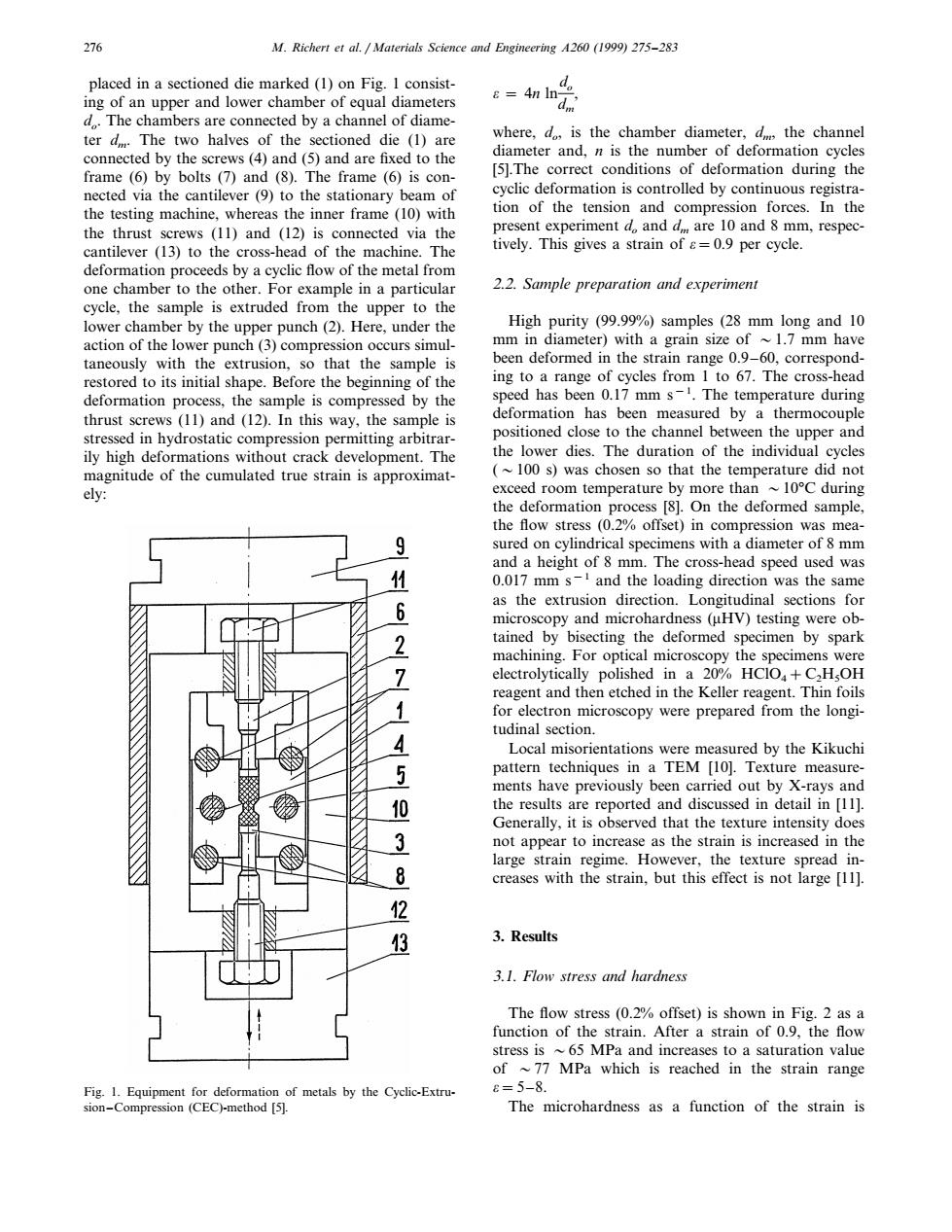
276 M.Richert et al.Materials Science and Engineering A260 (1999)275-283 placed in a sectioned die marked(1)on Fig.I consist- =4n In- ing of an upper and lower chamber of equal diameters d..The chambers are connected by a channel of diame- ter d.The two halves of the sectioned die (1)are where,d,is the chamber diameter,dm the channel connected by the screws (4)and (5)and are fixed to the diameter and,n is the number of deformation cycles frame(6)by bolts (7)and (8).The frame (6)is con- [5].The correct conditions of deformation during the nected via the cantilever (9)to the stationary beam of cyclic deformation is controlled by continuous registra- the testing machine,whereas the inner frame (10)with tion of the tension and compression forces.In the the thrust screws (11)and (12)is connected via the present experiment d,and d are 10 and 8 mm,respec- cantilever (13)to the cross-head of the machine.The tively.This gives a strain of s=0.9 per cycle. deformation proceeds by a cyclic flow of the metal from one chamber to the other.For example in a particular 2.2.Sample preparation and experiment cycle,the sample is extruded from the upper to the lower chamber by the upper punch(2).Here,under the High purity (99.99%)samples (28 mm long and 10 action of the lower punch(3)compression occurs simul- mm in diameter)with a grain size of ~1.7 mm have taneously with the extrusion.so that the sample is been deformed in the strain range 0.9-60,correspond- restored to its initial shape.Before the beginning of the ing to a range of cycles from I to 67.The cross-head deformation process,the sample is compressed by the speed has been 0.17 mm s-.The temperature during thrust screws (11)and (12).In this way,the sample is deformation has been measured by a thermocouple stressed in hydrostatic compression permitting arbitrar- positioned close to the channel between the upper and ily high deformations without crack development.The the lower dies.The duration of the individual cycles magnitude of the cumulated true strain is approximat- (~100 s)was chosen so that the temperature did not ely: exceed room temperature by more than ~10C during the deformation process [8].On the deformed sample, the flow stress (0.2%offset)in compression was mea- 9 sured on cylindrical specimens with a diameter of 8 mm and a height of 8 mm.The cross-head speed used was 1 0.017 mm s-and the loading direction was the same 6 as the extrusion direction.Longitudinal sections for microscopy and microhardness (uHV)testing were ob- 2 tained by bisecting the deformed specimen by spark machining.For optical microscopy the specimens were 7 electrolytically polished in a 20%HCIO+C2HsOH reagent and then etched in the Keller reagent.Thin foils 1 for electron microscopy were prepared from the longi- tudinal section. 4 Local misorientations were measured by the Kikuchi 5 pattern techniques in a TEM [10].Texture measure- ments have previously been carried out by X-rays and 10 the results are reported and discussed in detail in [11]. Generally,it is observed that the texture intensity does 3 not appear to increase as the strain is increased in the large strain regime.However,the texture spread in- 8 creases with the strain,but this effect is not large [11]. 2 3 3.Results 3.1.Flow stress and hardness The flow stress (0.2%offset)is shown in Fig.2 as a function of the strain.After a strain of 0.9,the flow stress is ~65 MPa and increases to a saturation value of ~77 MPa which is reached in the strain range Fig.1.Equipment for deformation of metals by the Cyclic-Extru- e=5-8. sion-Compression (CEC)-method [5]. The microhardness as a function of the strain is276 M. Richert et al. / Materials Science and Engineering A260 (1999) 275–283 placed in a sectioned die marked (1) on Fig. 1 consisting of an upper and lower chamber of equal diameters do. The chambers are connected by a channel of diameter dm. The two halves of the sectioned die (1) are connected by the screws (4) and (5) and are fixed to the frame (6) by bolts (7) and (8). The frame (6) is connected via the cantilever (9) to the stationary beam of the testing machine, whereas the inner frame (10) with the thrust screws (11) and (12) is connected via the cantilever (13) to the cross-head of the machine. The deformation proceeds by a cyclic flow of the metal from one chamber to the other. For example in a particular cycle, the sample is extruded from the upper to the lower chamber by the upper punch (2). Here, under the action of the lower punch (3) compression occurs simultaneously with the extrusion, so that the sample is restored to its initial shape. Before the beginning of the deformation process, the sample is compressed by the thrust screws (11) and (12). In this way, the sample is stressed in hydrostatic compression permitting arbitrarily high deformations without crack development. The magnitude of the cumulated true strain is approximately: o = 4n lndo dm , where, do, is the chamber diameter, dm, the channel diameter and, n is the number of deformation cycles [5].The correct conditions of deformation during the cyclic deformation is controlled by continuous registration of the tension and compression forces. In the present experiment do and dm are 10 and 8 mm, respectively. This gives a strain of o=0.9 per cycle. 2.2. Sample preparation and experiment High purity (99.99%) samples (28 mm long and 10 mm in diameter) with a grain size of 1.7 mm have been deformed in the strain range 0.9–60, corresponding to a range of cycles from 1 to 67. The cross-head speed has been 0.17 mm s−1 . The temperature during deformation has been measured by a thermocouple positioned close to the channel between the upper and the lower dies. The duration of the individual cycles (100 s) was chosen so that the temperature did not exceed room temperature by more than 10°C during the deformation process [8]. On the deformed sample, the flow stress (0.2% offset) in compression was measured on cylindrical specimens with a diameter of 8 mm and a height of 8 mm. The cross-head speed used was 0.017 mm s−1 and the loading direction was the same as the extrusion direction. Longitudinal sections for microscopy and microhardness (mHV) testing were obtained by bisecting the deformed specimen by spark machining. For optical microscopy the specimens were electrolytically polished in a 20% HClO4+C2H5OH reagent and then etched in the Keller reagent. Thin foils for electron microscopy were prepared from the longitudinal section. Local misorientations were measured by the Kikuchi pattern techniques in a TEM [10]. Texture measurements have previously been carried out by X-rays and the results are reported and discussed in detail in [11]. Generally, it is observed that the texture intensity does not appear to increase as the strain is increased in the large strain regime. However, the texture spread increases with the strain, but this effect is not large [11]. 3. Results 3.1. Flow stress and hardness The flow stress (0.2% offset) is shown in Fig. 2 as a function of the strain. After a strain of 0.9, the flow stress is 65 MPa and increases to a saturation value of 77 MPa which is reached in the strain range o=5–8. The microhardness as a function of the strain is Fig. 1. Equipment for deformation of metals by the Cyclic-Extrusion–Compression (CEC)-method [5].�����