正在加载图片...
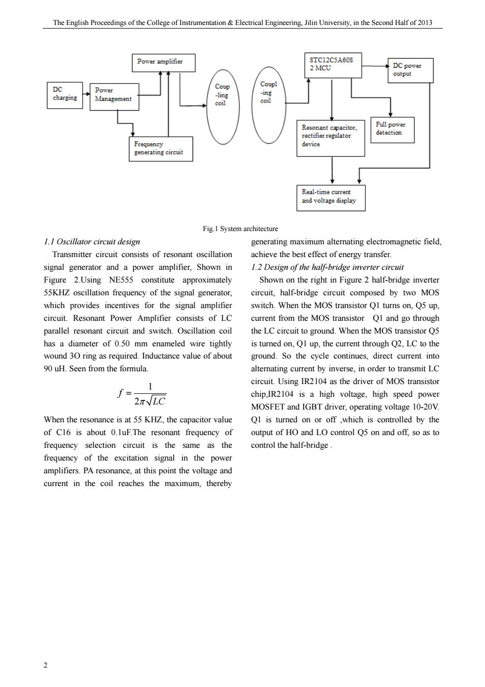
The English Proceedings of the College of Instrumen ation Electrical Engi eering.Jiin University,in the Second Halfof2013 Raltiecra Fig.I System architecture generating maximum altemating field consists of resonant achieve the best signal generator and a power amplifier,Shown in 1.2 Design of the half-bridge inverter circui Figure 2.Using NE555 constitute approximately Shown on the right in Figure 2 half-bridge inverter 55KHZ oscillation frequency of the signal generator, eireuit,half-bridge eircuit composed by two MOS which provides incentives for the signal amplifier switch.When the MOS transistor QI turns on,Q5 up circuit Resonant Power consists of LC current from the MOS transistor and go throug parallel resonant circuit and switch.Oscillation coil the LC circuit to ground.When the MOS transistor Q has a diameter of 0.50 mm enameled wire tightly is turned on,Q1 up,the current through Q2,LC to the wound 30 ring as required.Inductance value of about ground.So the cycle continues.direct current into 90 uH.Seen from the formula. alternating current by inverse.in order to transmit LC 1 circuit.Using IR2104 as the driver of MOS transistor f= chip.is a high voltage. When the resonance is at 55 KHZ,the capacitor value Q1 is turned on or off,which is controlled by the of C16 is about 0.luF.The resonant frequency of output of HO and LO control Q5 on and off,so as to control the half-bridge of the excitation signal in the e powe amplifiers.PA resonance,at this point the voltage and current in the coil reaches the maximum,thereby 2 期 The English Proceedings of the College of Instrumentation & Electrical Engineering, Jilin University, in the Second Half of 2013 2 Fig.1 System architecture 1.1 Oscillator circuit design Transmitter circuit consists of resonant oscillation signal generator and a power amplifier, Shown in Figure 2.Using NE555 constitute approximately 55KHZ oscillation frequency of the signal generator, which provides incentives for the signal amplifier circuit. Resonant Power Amplifier consists of LC parallel resonant circuit and switch. Oscillation coil has a diameter of 0.50 mm enameled wire tightly wound 3O ring as required. Inductance value of about 90 uH. Seen from the formula. 1 2 f π LC = When the resonance is at 55 KHZ, the capacitor value of C16 is about 0.1uF.The resonant frequency of frequency selection circuit is the same as the frequency of the excitation signal in the power amplifiers. PA resonance, at this point the voltage and current in the coil reaches the maximum, thereby generating maximum alternating electromagnetic field, achieve the best effect of energy transfer. 1.2 Design of the half-bridge inverter circuit Shown on the right in Figure 2 half-bridge inverter circuit, half-bridge circuit composed by two MOS switch. When the MOS transistor Q1 turns on, Q5 up, current from the MOS transistor Q1 and go through the LC circuit to ground. When the MOS transistor Q5 is turned on, Q1 up, the current through Q2, LC to the ground. So the cycle continues, direct current into alternating current by inverse, in order to transmit LC circuit. Using IR2104 as the driver of MOS transistor chip,IR2104 is a high voltage, high speed power MOSFET and IGBT driver, operating voltage 10-20V. Q1 is turned on or off ,which is controlled by the output of HO and LO control Q5 on and off, so as to control the half-bridge