正在加载图片...
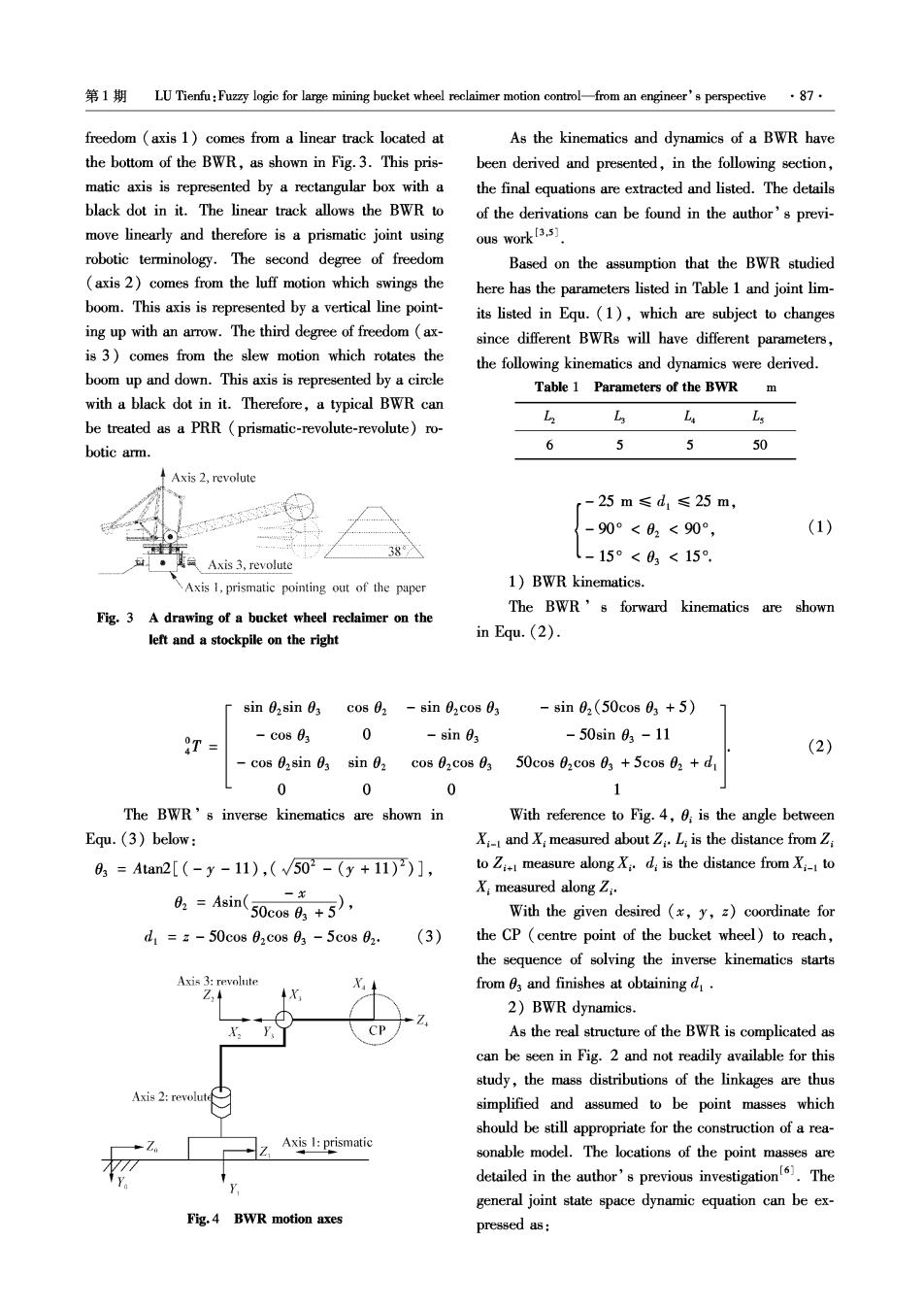
第1期LU Tienfu:Fuz☒logic for large mining bucket wheel reclaimer motion contro--from an engineer's perspective·87· freedom (axis 1)comes from a linear track located at As the kinematics and dynamics of a BWR have the bottom of the BWR,as shown in Fig.3.This pris- been derived and presented,in the following section, matic axis is represented by a rectangular box with a the final equations are extracted and listed.The details black dot in it.The linear track allows the BWR to of the derivations can be found in the author's previ- move linearly and therefore is a prismatic joint using ous work[3.5] robotic terminology.The second degree of freedom Based on the assumption that the BWR studied (axis 2)comes from the luff motion which swings the here has the parameters listed in Table 1 and joint lim- boom.This axis is represented by a vertical line point- its listed in Equ.(1),which are subject to changes ing up with an arrow.The third degree of freedom (ax- since different BWRs will have different parameters, is 3)comes from the slew motion which rotates the the following kinematics and dynamics were derived. boom up and down.This axis is represented by a circle Table 1 Parameters of the BWR with a black dot in it.Therefore,a typical BWR can L L be treated as a PRR (prismatic-revolute-revolute)ro- botic arm. 6 5 5 50 ↑Axis2,revolute r-25m≤d1≤25m, -90°<02<90°, (1) Axis 3,revolute l-15°<03<15°, Axis 1,prismatic pointing out of the paper 1)BWR kinematics. The BWR's forward kinematics are shown Fig.3 A drawing of a bucket wheel reclaimer on the left and a stockpile on the right in Equ.(2). sin 02sin 0 cos 02 sin 02cos 0 -8in02(50cos03+5) T -C0883 0 -sin 03 -50sin03-11 (2) cos 0,sin 0 sin 0, c0802c0803 50cos 02cos 03 +5cos 02+d 0 0 0 1 The BWR's inverse kinematics are shown in With reference to Fig.4,0;is the angle between Equ.(3)below: X-I and X;measured about ZL;is the distance from Z 6,=Aan2[(-y-11),(√502-(y+11))], to Z measure along Xd is the distance from X to &=4sin(50eni6+5, X:measured along Z:. With the given desired (x,y,z)coordinate for d1=z-50cos02c0803-5cos02: (3) the CP (centre point of the bucket wheel)to reach, the sequence of solving the inverse kinematics starts Axis 3:revolute from 03 and finishes at obtaining d. Z. X 2)BWR dynamics. CP As the real structure of the BWR is complicated as can be seen in Fig.2 and not readily available for this study,the mass distributions of the linkages are thus Axis 2:revolute simplified and assumed to be point masses which should be still appropriate for the construction of a rea- Axis 1:prismatic sonable model.The locations of the point masses are detailed in the author's previous investigation.The general joint state space dynamic equation can be ex- Fig.4 BWR motion axes pressed as: